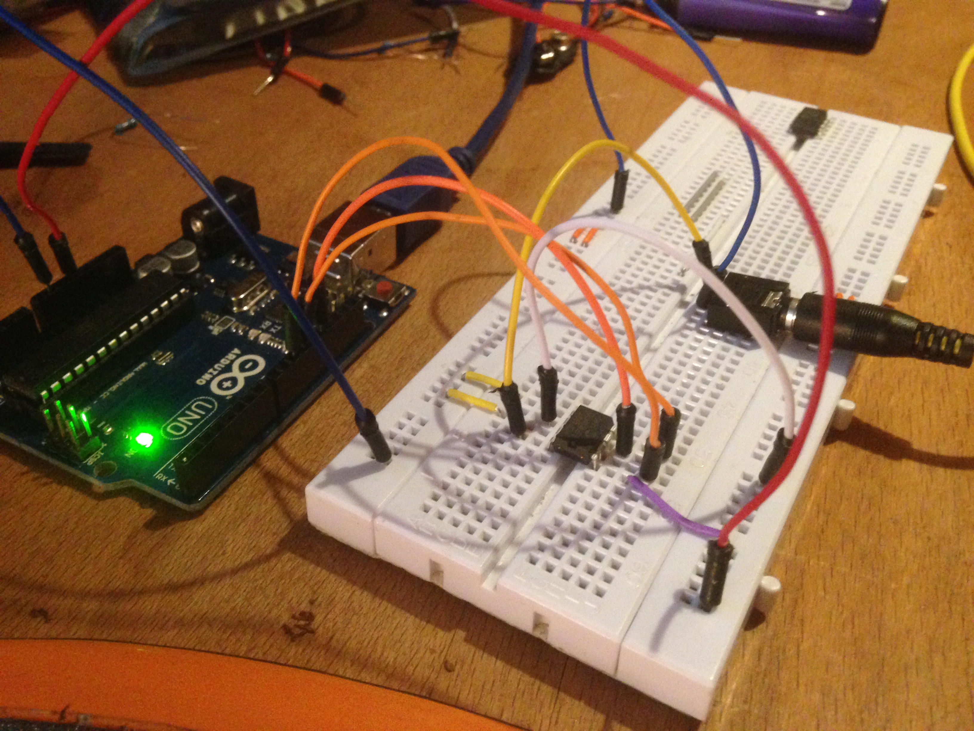
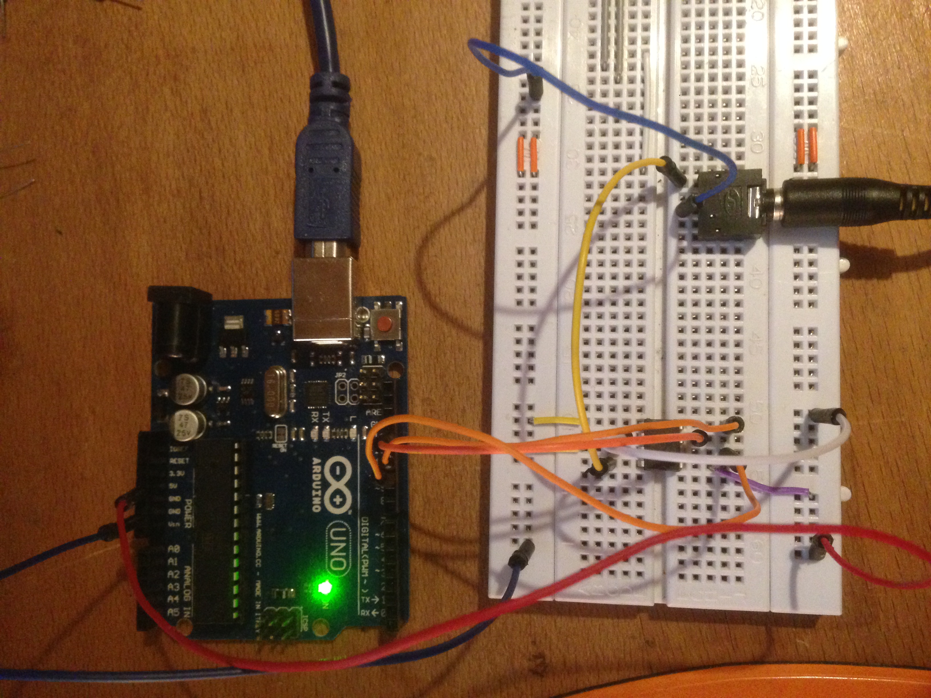
I thought I’d share some experimentation I’ve been doing with the Arduino and a 12 bit dac (mcp4921).
I’d been looking for things I could do with it and one obvious thing that came to mind was creating a sync signal for the Volca’s.
I analysed the output of the sync signal from the SQ-1 as best I could with a multimeter and could see that the signal was peaking around 0.32 volts.
Now if I could get the dac to output a voltage somewhere in that range at a regular interval I’d be able to control the Volca’s tempo from the Arduino.
The mcp4921 connects to the Arduino via SPI. Here I’m using pins 10 (CS to dac pin 2), 11 (SDI/MOSI to dac pin 4) & 13 (CLK to dac pin 3).
The rest of the dac pins are configured as follows;
pin 1 to Arduino +5v
pin 5 to Arduino ground
pin 6 Voltage reference to Arduino +5v
pin 7 to Arduino ground
pin 8 dac output to positive on headphone jack
Arduino & MCP4921 DAC Syncer for Korg Volca’sArduino & MCP4921 DAC Syncer for Korg Volca’s
The sketch employs a delay between setting the signal high and low which is set by the value of the variable tempo_delay. The delay is in ms and converting from bpm to the correct ms delay is simply as case of using the following formula. tempo_delay = (60,000 / BPM) /2.
I’ve posted a video to YouTube tonight of some of my breadboard experiments with CMOS logic chips as DIY synth oscillators (CD40106 & CD4093) connected to the Korg SQ-1.
I’ll be sure to post my thoughts and comments on this device once I’ve had a chance to play with it.
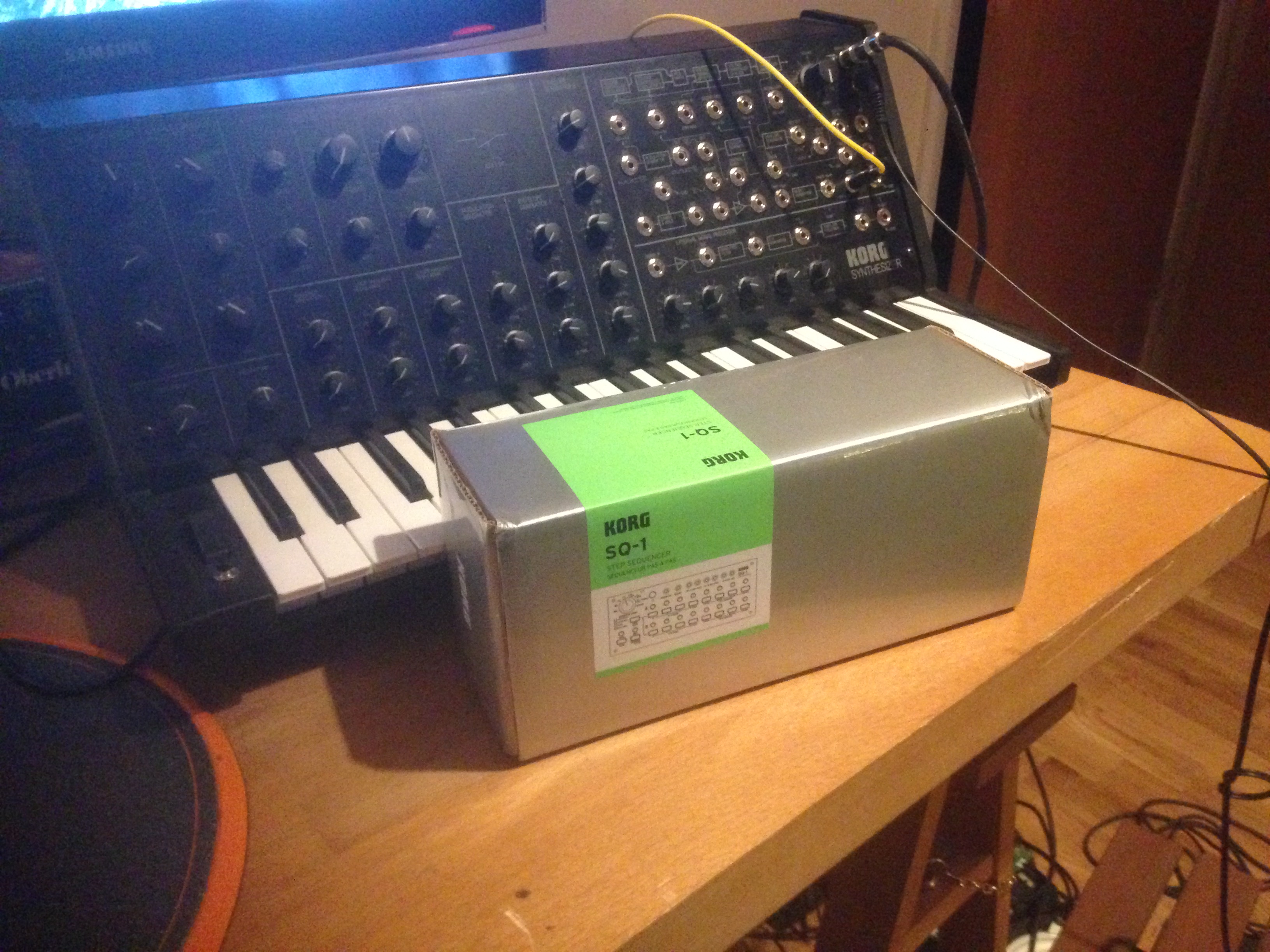
Korg SQ-1 and MS-20 Mini
Korg SQ-1 kit contents, two cheap batteries and a mini jack to MIDI cable.
There is a USB port on the back which might be able to provide power but interestingly the unit takes 2 AA batteries, 3v.
MIDI operates at 5v and the CV on the MS-20 I believe is 8v so Korg are obviously doing something devious here to save power. Possibly using some sort of ‘joule theif’. Interesting.
Check back for updates to this post with more information as it becomes known.
I’ve been trying a few different methods of connecting modern hard drives to my E-MU sampler. My aim, to reduce the noise to an absolute minimum with the side benefit of possible requiring less power from the ageing PSU.
Power
One of the quirks of the e-mu e5000 ultra and other samplers in the range, is that the power output header on the motherboard for internal hard disks has had it’s pins reversed in order of a standard PC. Plugging in a hard drive to the sampler and turning it on without modifying the power cable will result in +12v being where your hard drive expected +5v and a puff of magic smoke will signal the death of your hard drive.
SATA to IDE coverters
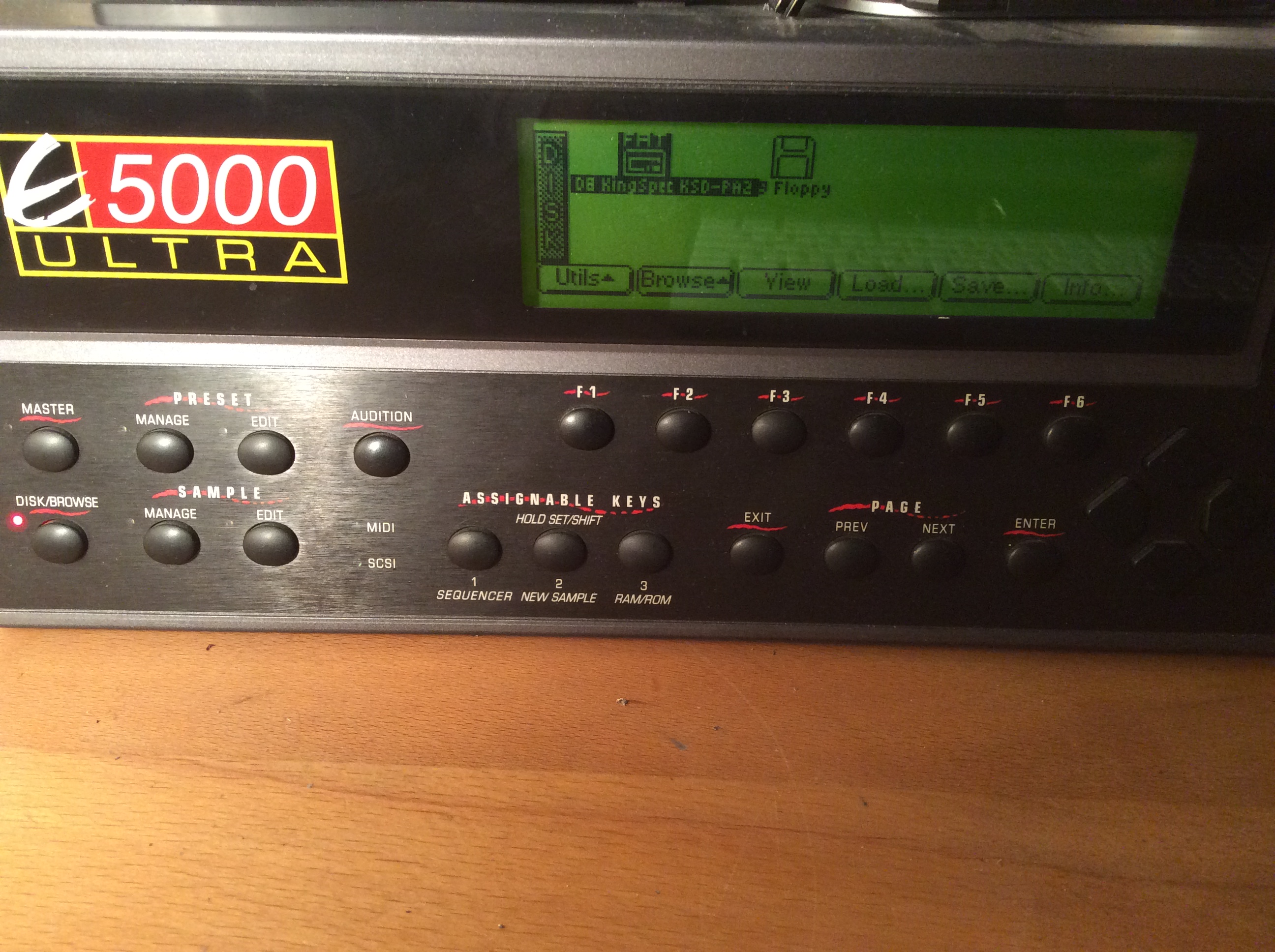
I tried several different converters without success until I came across the WinTech 93205-GB which worked great with standard 2.5″ spinning SATA disks but although SATA SSD drives were detected by the sampler they were not able to be formatted or accessed when pre-formatted as FAT.
The WinTech has a slide switch to select between host and device. Device was selected.
Wintech 93205-GB SATA to IDE Converter
The fix for the reverse power connection was simple, clip through all the cables and connect the red to the yellow and the yellow to the red, swap the ground cables and test with a multimeter to make sure I hadn’t made any mistakes. I took this opportunity to also solder in the tiny 5v power connector for the WinTech in series from the 5v power cable and ground.
Doctored power cable
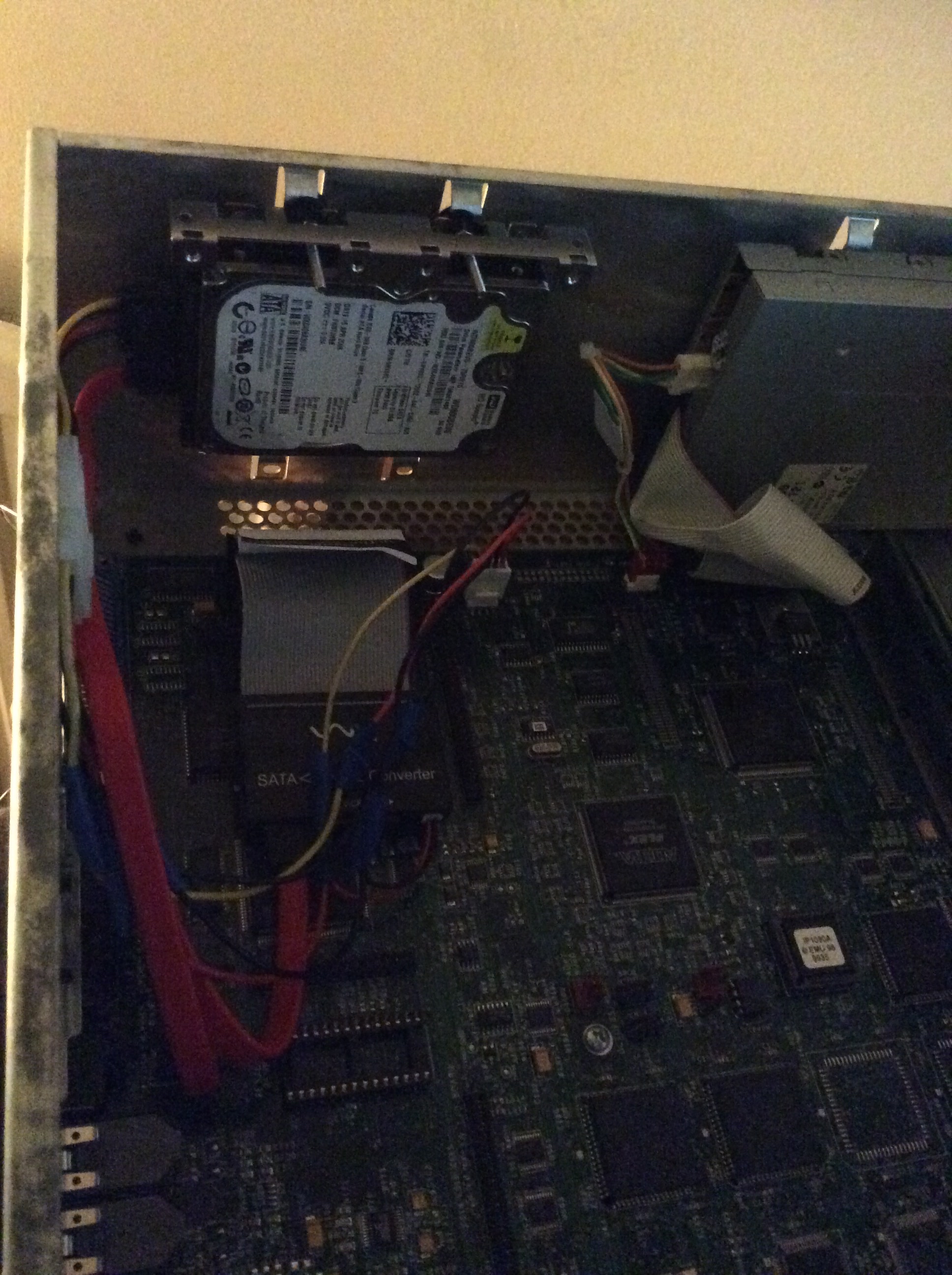
To connect the hard drive to the case I used a 2.5″ to 3.5″ mounting bracket with rubber washer to reduce vibration noise and fixed to the top mounting holes for a 3.5″ disk.
Mounted in position
Lovely, barely a sound and worked flawlessly.
I wanted more though.
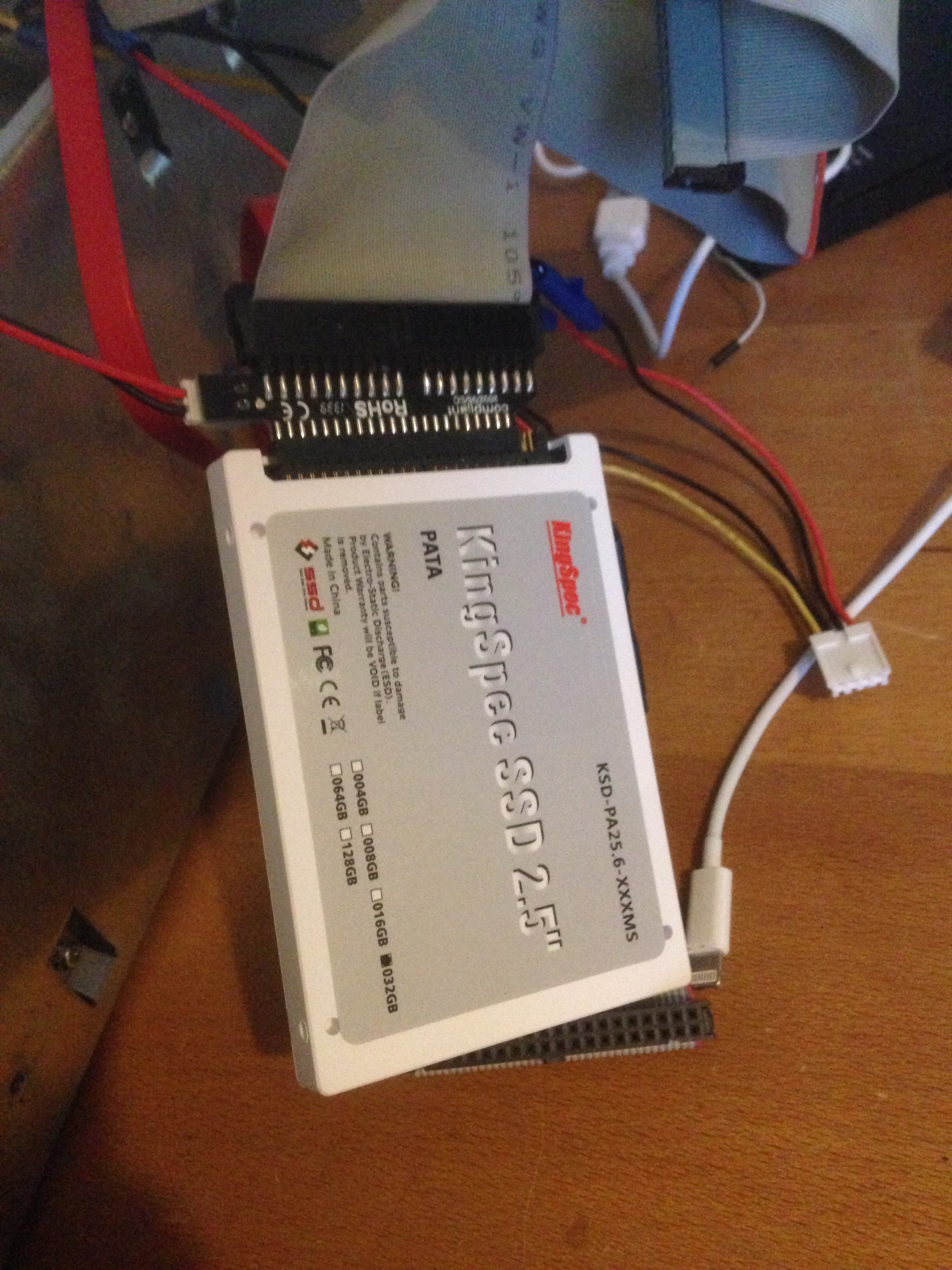
PATA SSD
I took to google in a quest to find myself a IDE/PATA SSD hoping that it just might work.
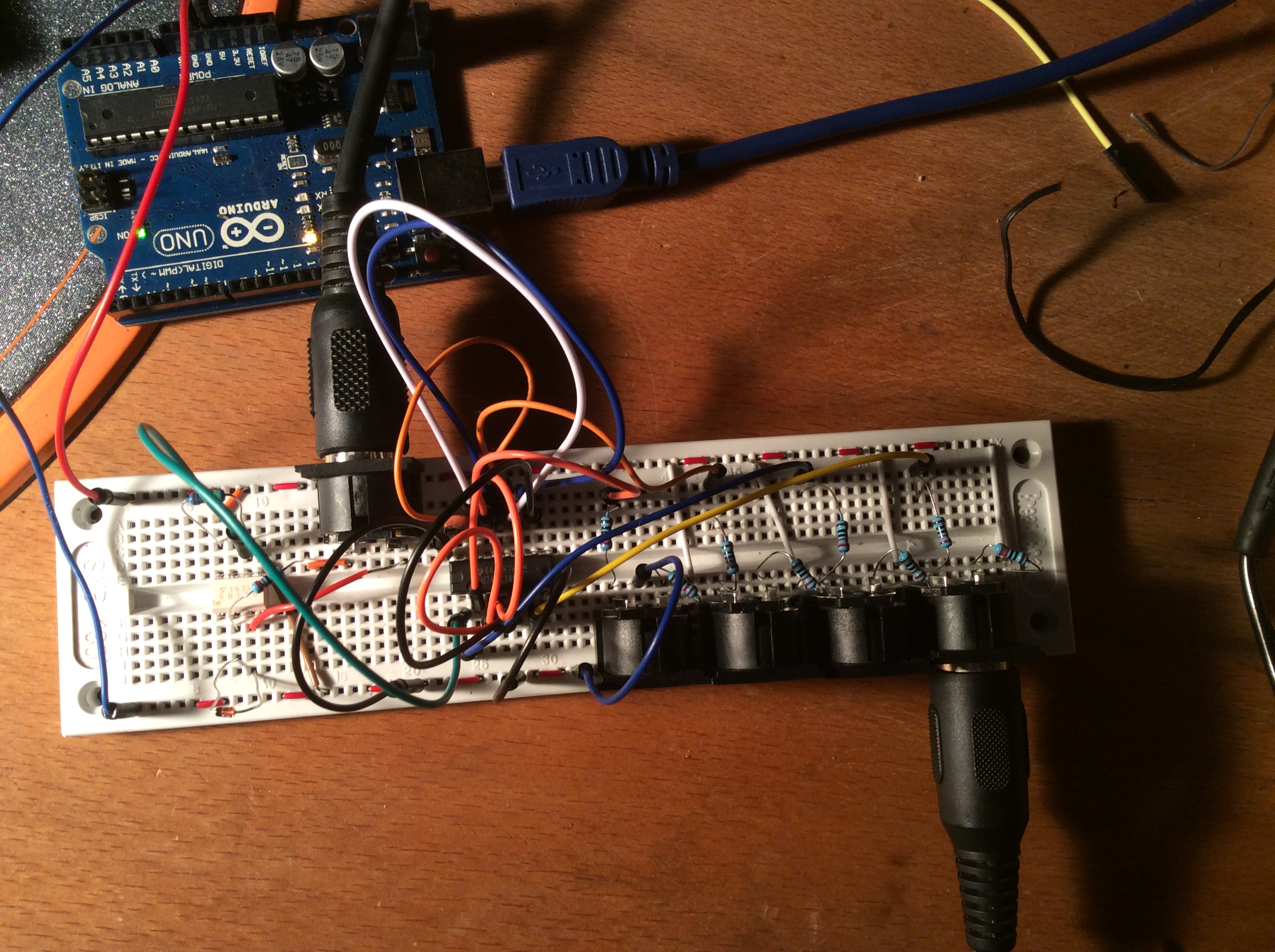
Tonight I’ve been trying to decipher the various schematics online for creating a midi thru box. My knowledge of electronics is growing but still very basic and even such a simple circuit gave me some headaches.
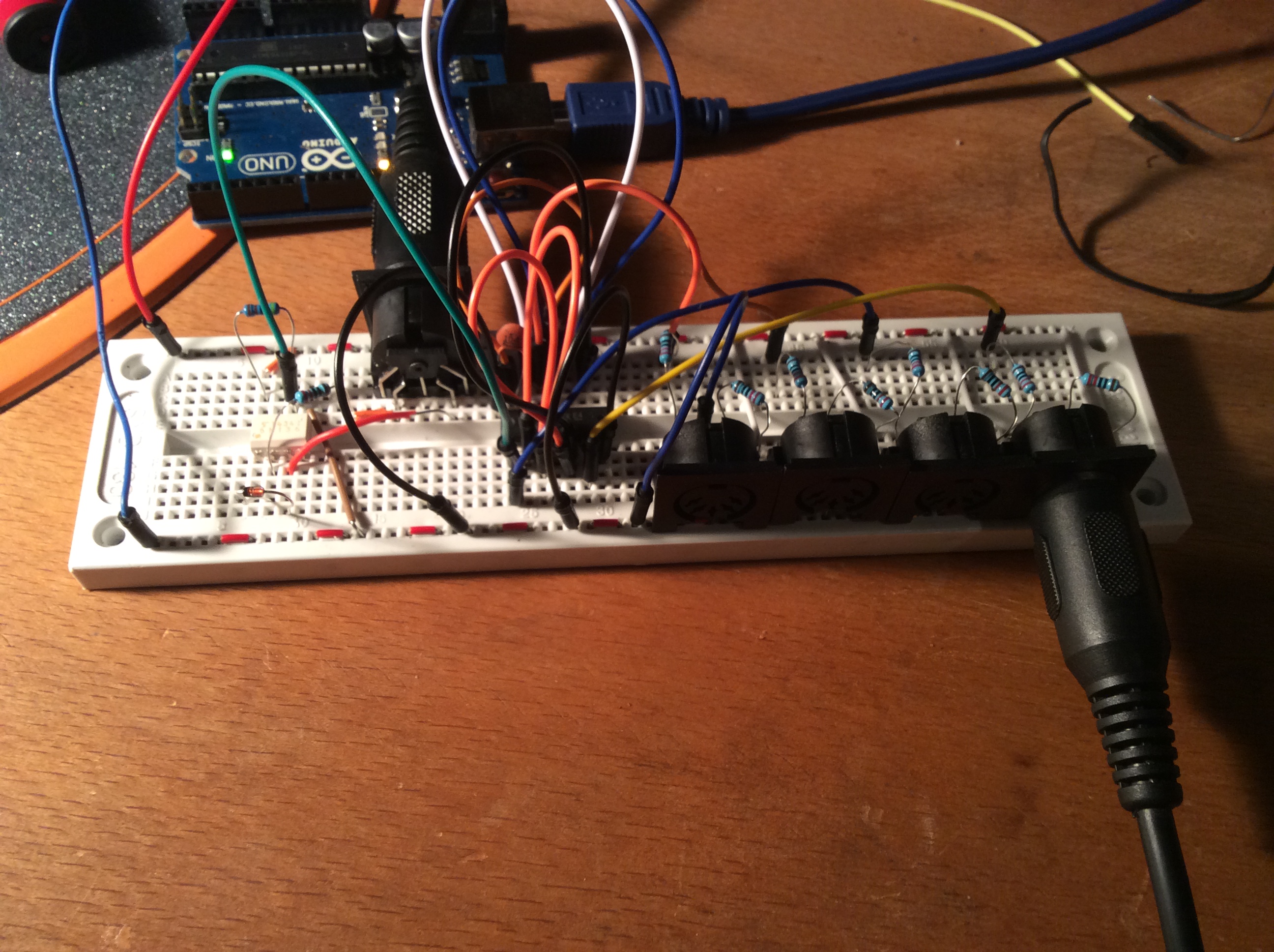
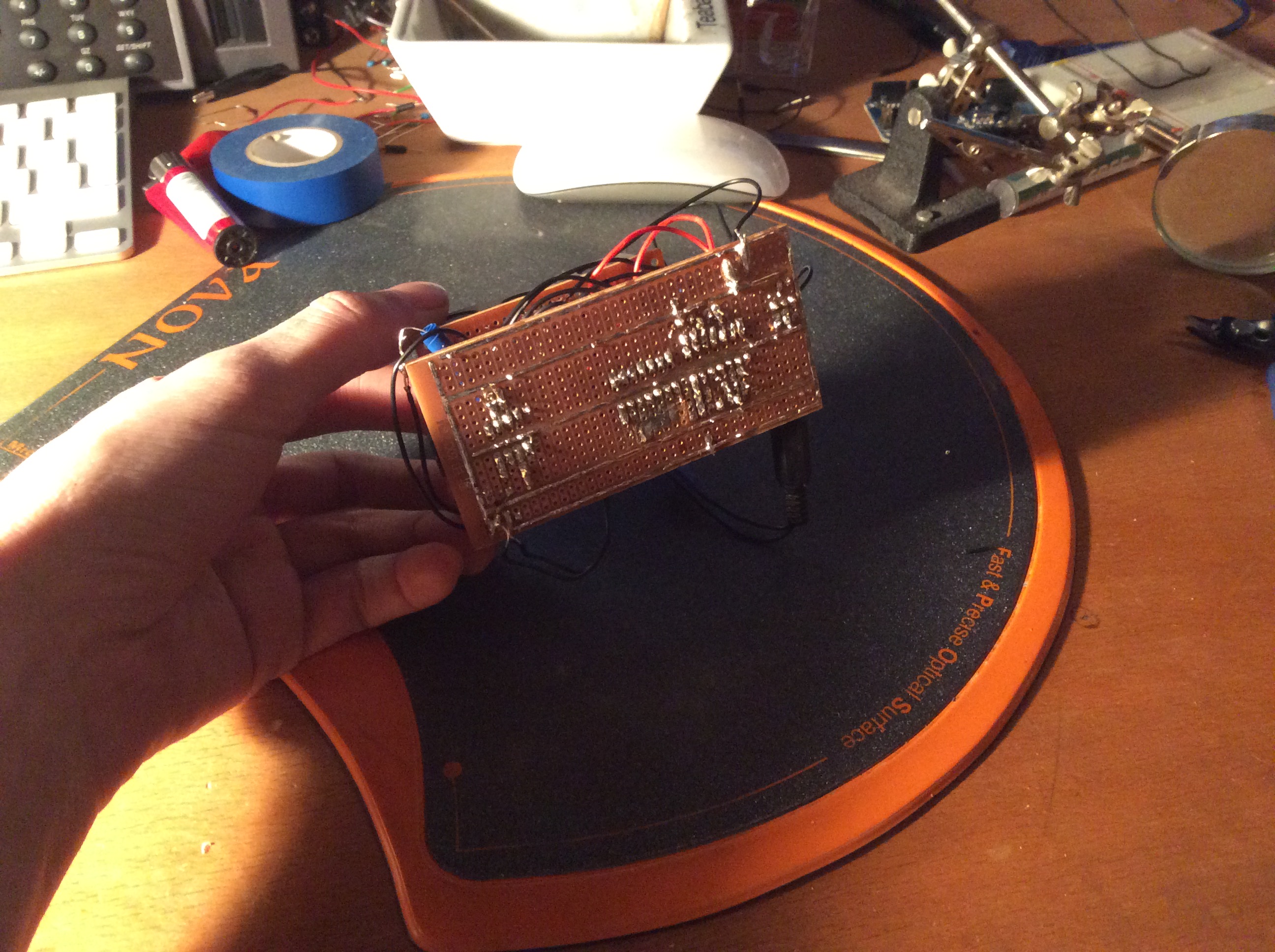
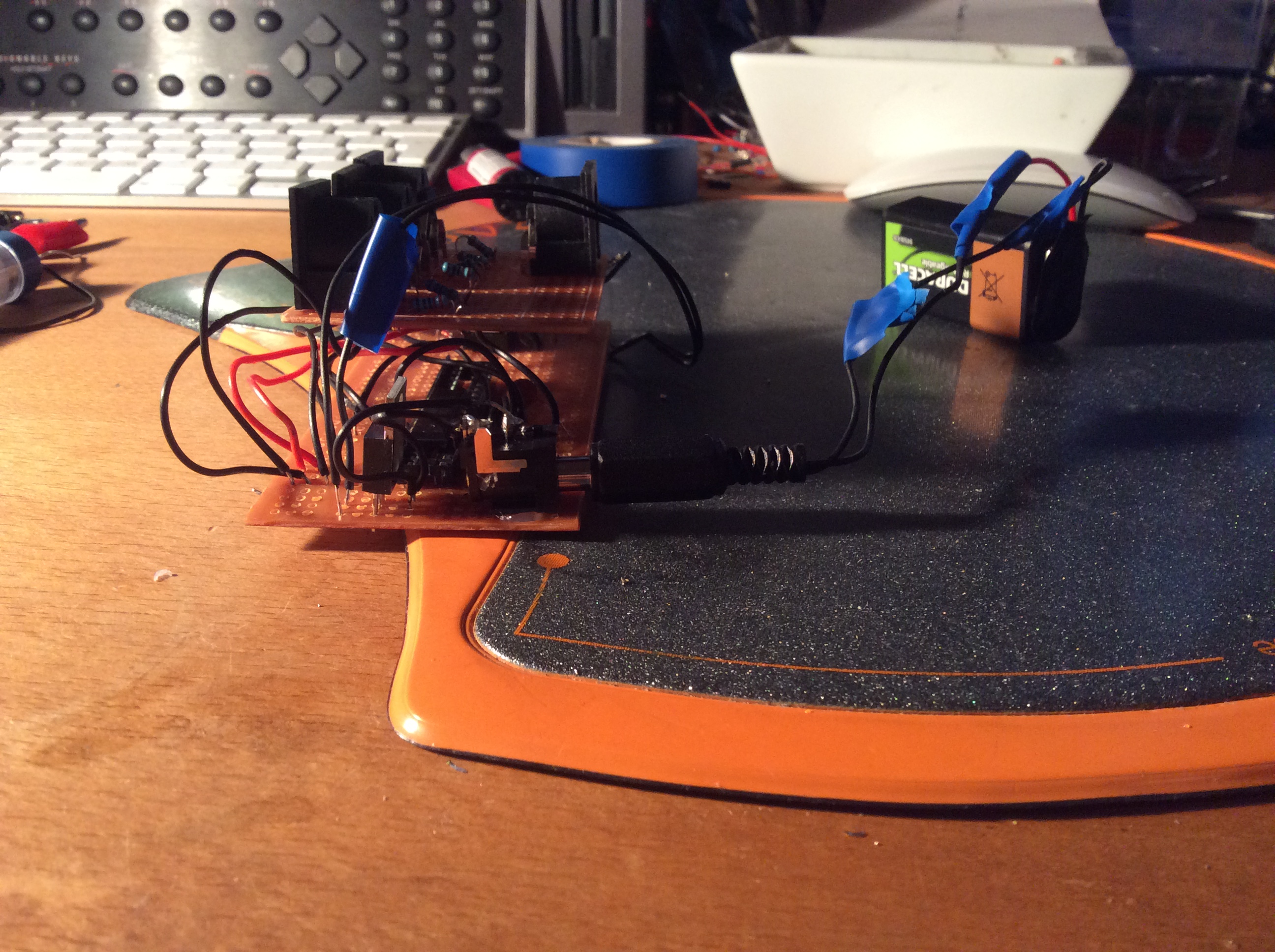
So here it is, a working midi thru, ignore the Arduino connected to the breadboard it’s only being used to supply 5v and nothing else. The soldered circuit board bellow has a 9v battery/mains input.
Bill of materials:
5 x MIDI connectors
1 x 6N136 optocoupler
1 x 74CH14 Hex schmitt inverter (or CD40106)
9 x 220 ohm resistor
1 x 4.7k ohm resistor
1 x 1n4148 diode
1 x TS7805 5v power regulator
1 x 2.1 mm power header
And then solder to perfboard circuit board. It’s certainly not pretty and some of the worst soldering I’ve ever seen but it works. 🙂
All I need now is some sort of case and I’m good to go.
I’ll try and update this post with more detail and clearer breadboard layout / schematic when I get the time.
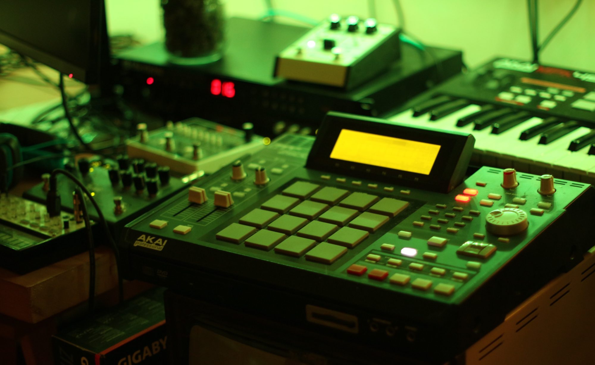
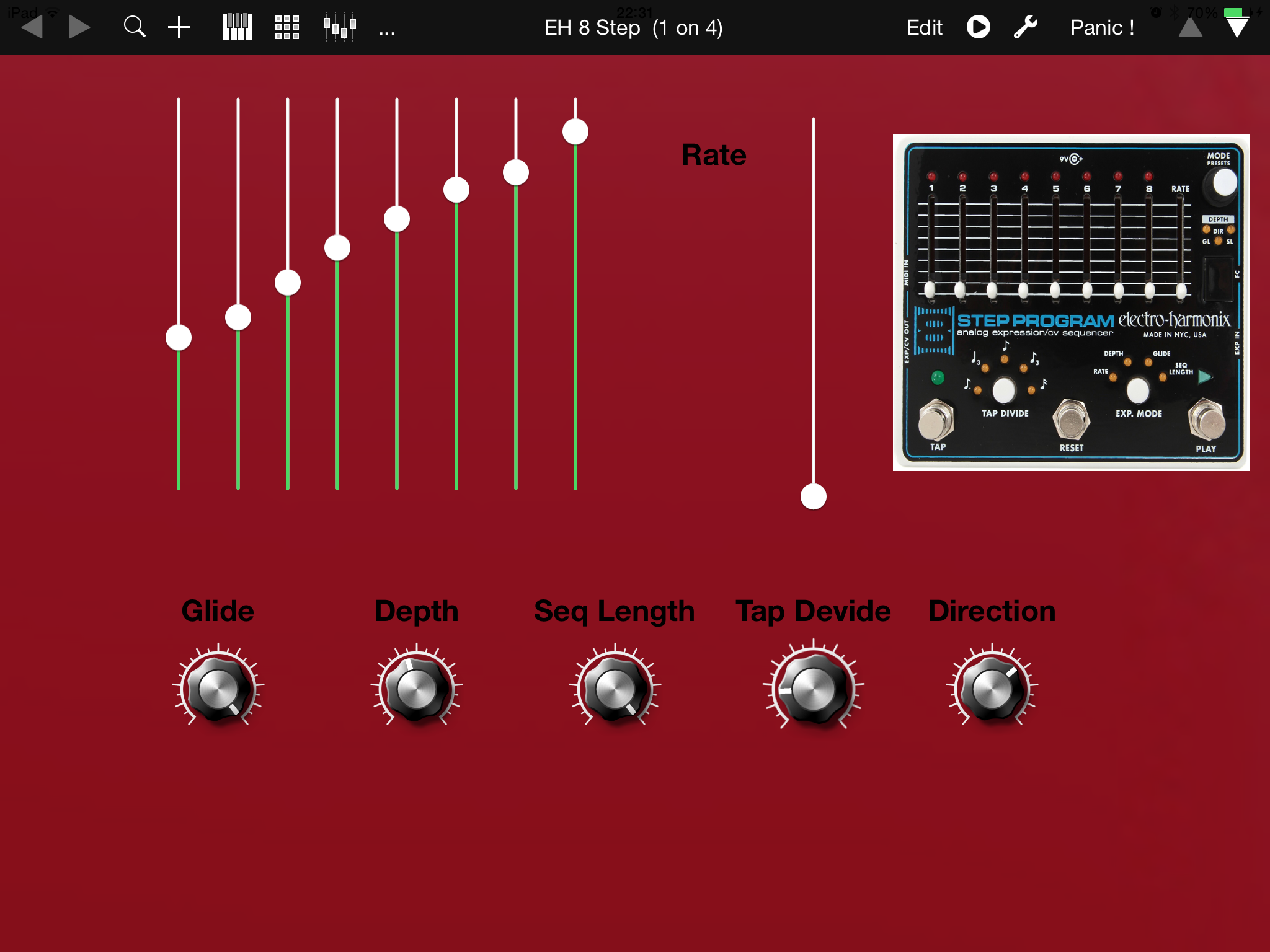
Tonight I created an iPad MIDI control surface for the 8 step using tb midi stuff which I’ve talked about in previous posts.
Here is a link to version 0.1 of the template with just the very basics implemented. The 8 step has a surprising amount of depth to the midi control. Download
I made a brief video on some of the integration between the Electro Harmonix 8 step and the Korg Ms-20 Mini.
The 8 step is an 8 step CV sequencer which can be synced and controlled via MIDI.
Here I take a look at replacing the MS-20 Mini internal LFO with a MIDI synced ‘lfo’ from the Electro Harmonix to control the low pass filter and frequency modulation.
I’ve recently been exploring the musical possibilities of the iPad and one of my recent discoveries has been the fantastic TB MidiStuff.
It allows you to easily create touch interfaces for your MIDI devices. Combined with the wireless midi functions of the iPad and OS X and it makes controlling MIDI devices wirelessly easy enough even for me.
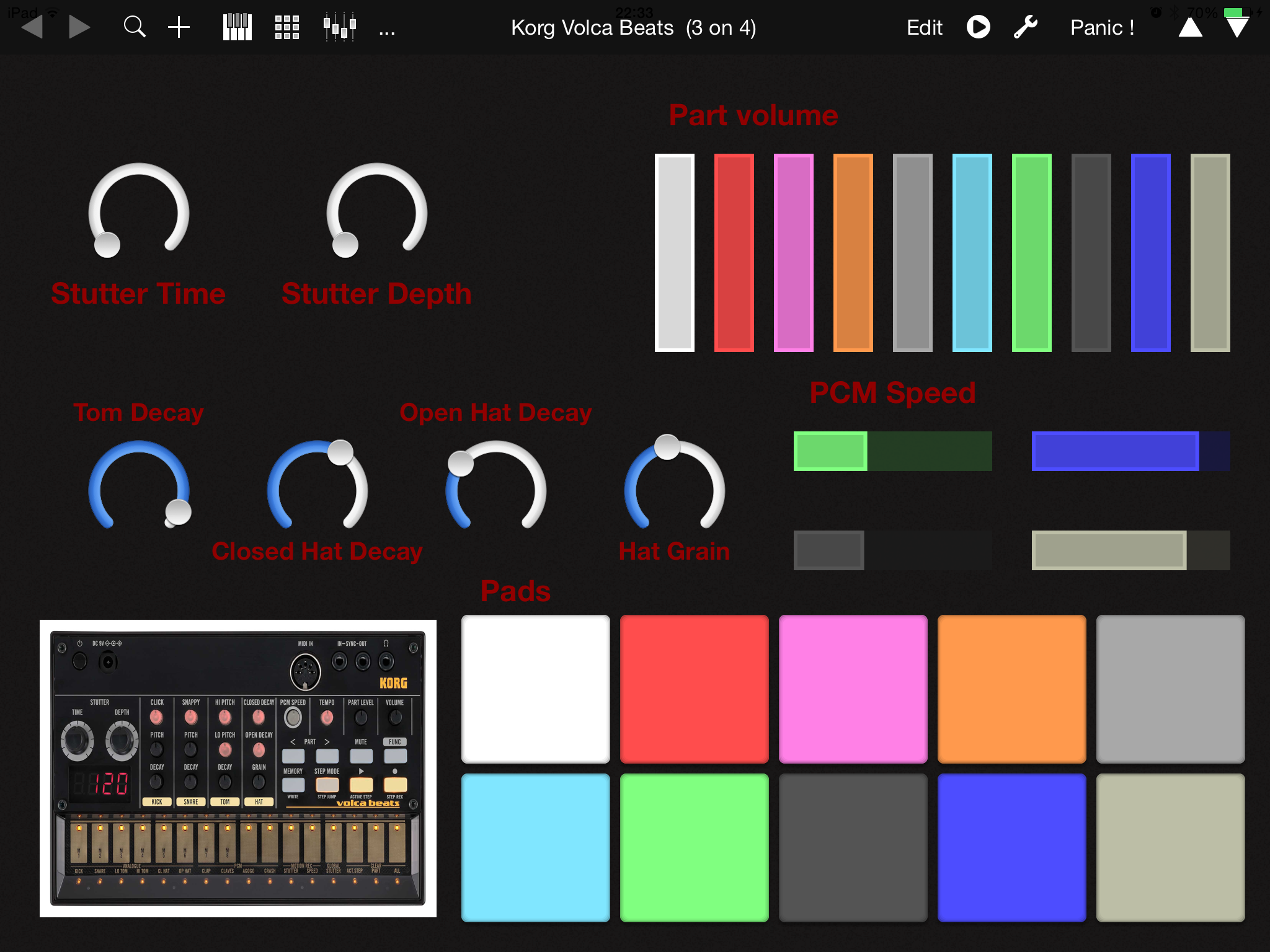
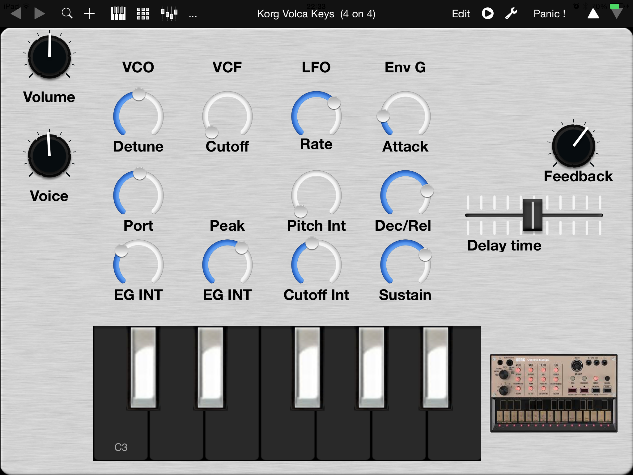
Tonight I sat down to explore what was on offer. I’ve got to say I’ve not even scratched the surface but in the process I created two “panels” for controlling the Volca Beats and the Volca Keys.
Unfortunately not every knob on the Volca’s is accessible from MIDI. The Volca Keys is missing the VCF Peak and the Beats is missing some of the most useful for shaping the sound, the kick click, pitch and decay, snare snap, pitch and decay, tom hi pitch, tom lo pitch. Obviously this has been done to save costs but it still gives us plenty to twiddle with.
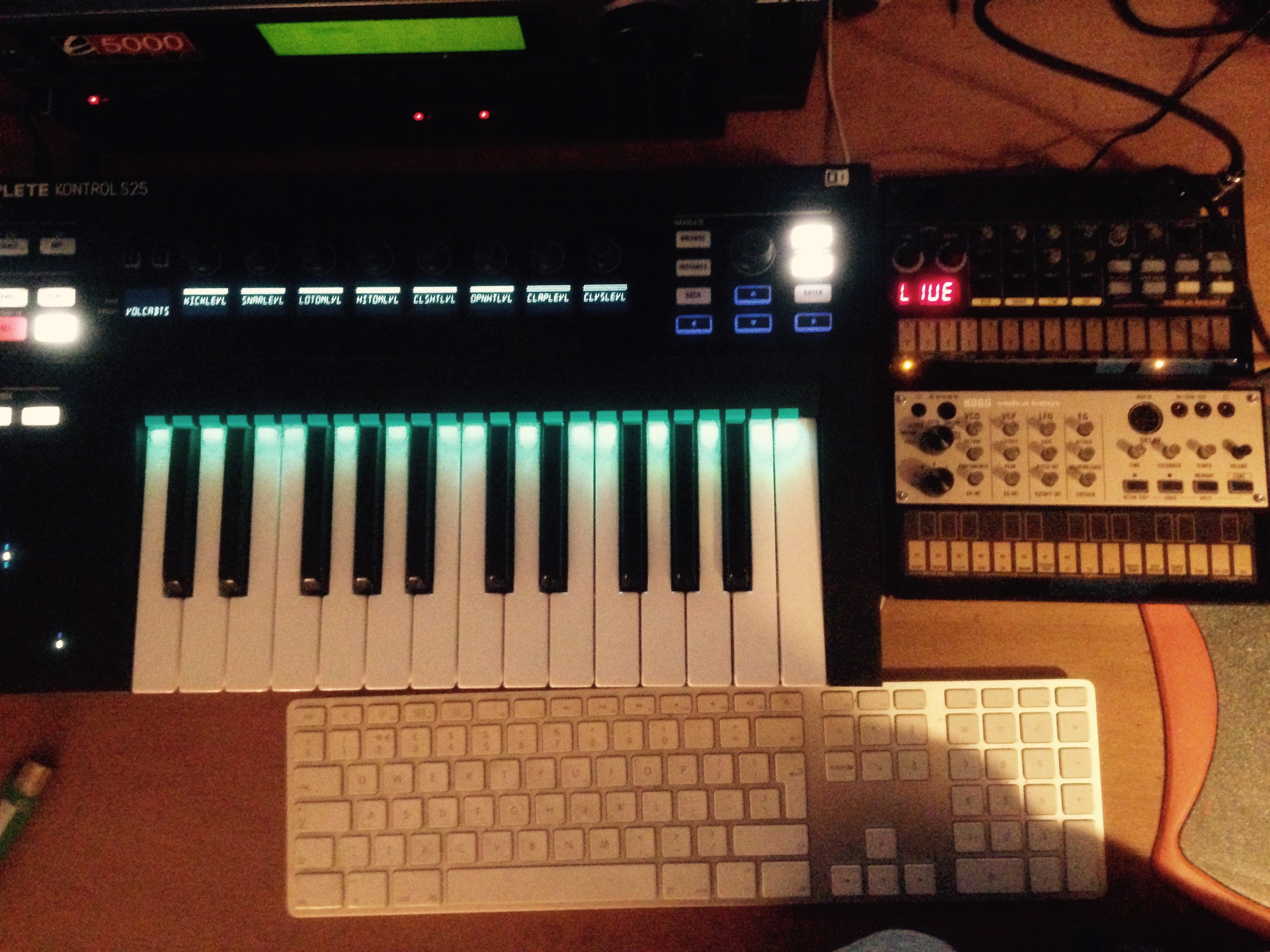
I wanted to share a few templates I’ve made for the Volca Beats and Volca Keys for the NI Komplete Kontrol S25 keyboard.
So far I can’t see how to use to assign more than 8 knobs per template so I’ve had to split them out across multiple template.
This is a major blow as so far it looks like you’ll need to take your hands off the keyboard and use your mouse to select between templates. Controller values will also rest to 0 when changing from template to template.
This could be fixed if we could use the bank select button next to the knobs but NI knows best. Hmmm.
I’ll be sure to update this post if I manage to overcome the seemingly bonkers restriction.
Here’s a list of the midi controls the volca’s offer:
PART LEVEL ADJUSTMENTS
(KICK, SNARE, LO TOM, HI TOM, CL HAT,
OP HAT, CLAP, CLAVES, AGOGO, CRASH)
PCM SPEED
(CLAP, CALVES, AGOGO, CRASH)
STUTTER TIME
STUTTER DEPTH
TOM DECAY
CLOSED HAT DECAY
OPEN HAT DECAY
Annoyingly there is no option for kick or snare pitch or decay. Could there be a way to mod this?
Hello all, I thought I’d document the process of replacing the noisy power supply fan in my E-MU E5000 Ultra sampler with some pictures in the hope that it may be of use to others out there.
All credit goes to GaemethProject‘s video on YouTube for giving me the confidence to try this myself.
First off you’ll need the following tools and components;
It’s worth keeping in mind that the large capacitors in power supplies can retain a charge for some considerable time after being powered off so make sure to wait at least a few hours with the machine turned off and unplugged before attempting access to the power supply. I’m probably over cautious but I’d like to wait at least a day.
Once an appropriate amount of time has passed, you can begin by removing the 7 screws holding the case lid in place, 2 on each side and then 3 at the top of the rear.
Now that you have access to the inside of the case, you can move to the back and start unscrewing the screws which hold the power supply housing in place. Make sure not to undo the two screws holding the fan in-place until after you have removed the power supply housing.
(Screws holding E-MU E5000 Ultra fan and psu housing in place)
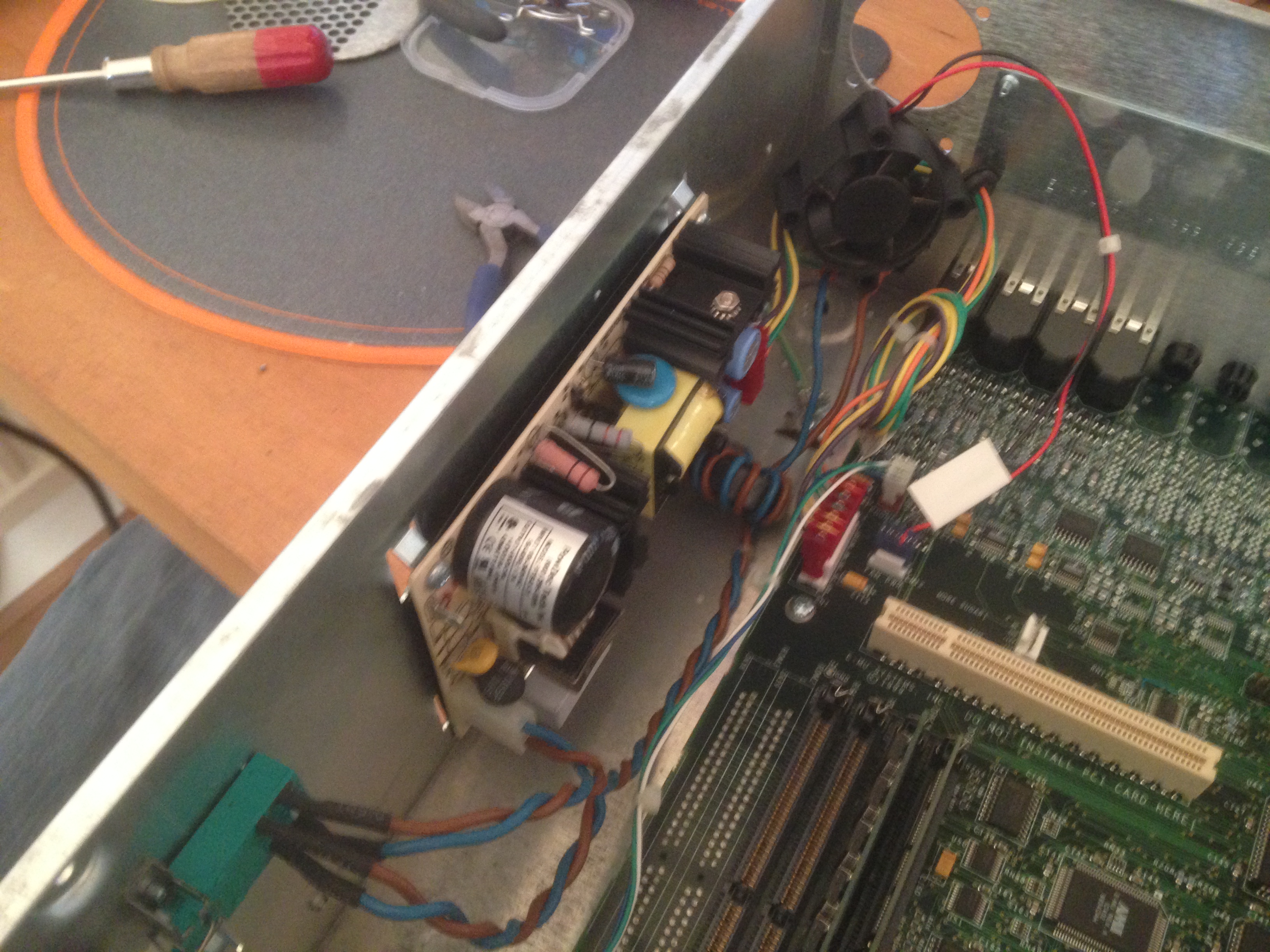
Now with a bit of jiggling you will be able to remove the power supply housing, be careful not to damage any of the cables which are threaded through the housing or the on off switch which is partially housed behind the power supply case but does not need to be removed.
(The power supply revealed)
You can now unplug the fan from the header pins on the motherboard and throw it in the bin. (Ok, you can keep it if you want to but why would you want to?)
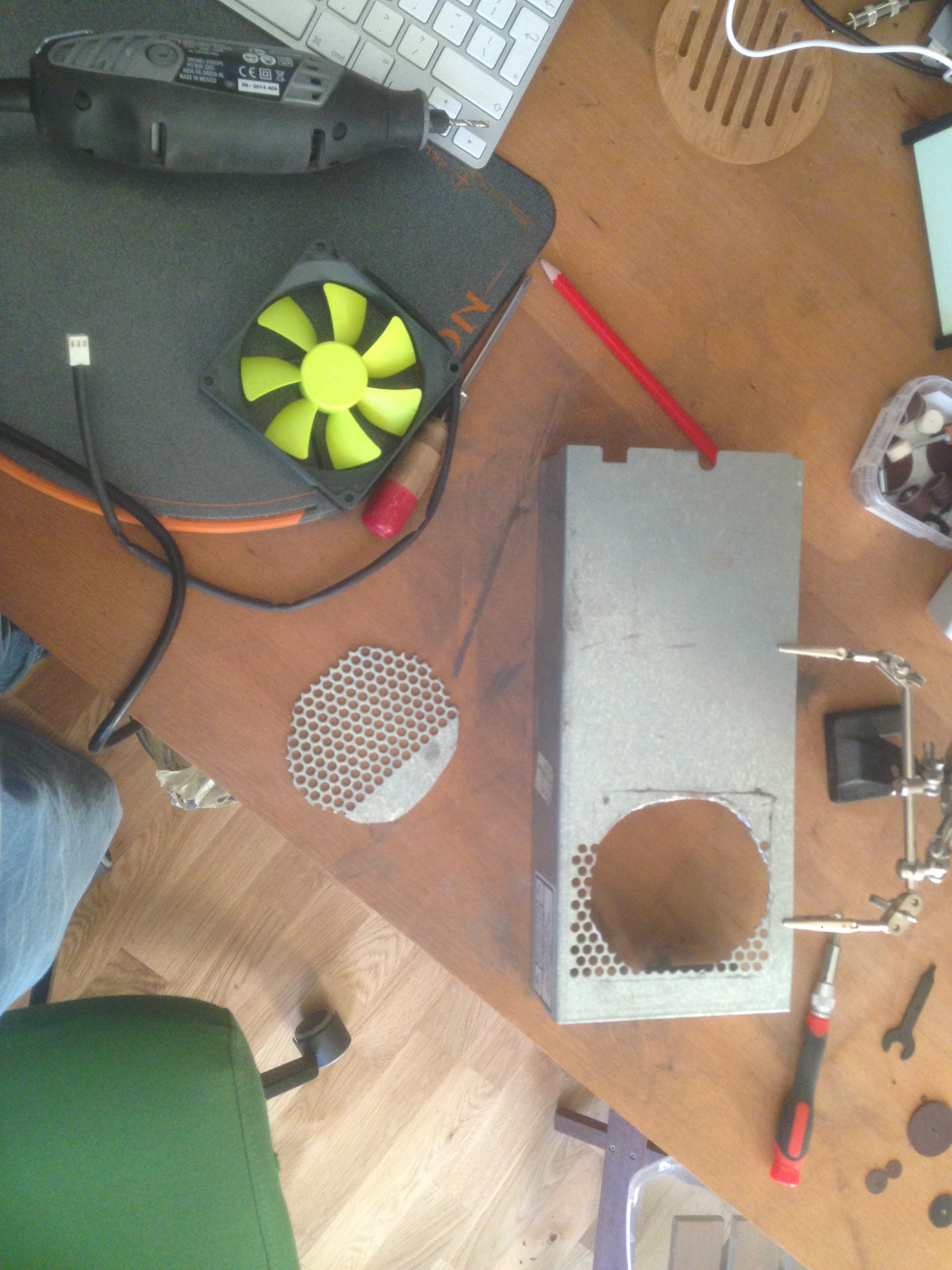
Now that you have the power supply housing free it’s time to get busy with the Dremel. Try positioning your new fan over the grill to to see where it will fit best. You should be able to use two of the holes in the grill for two of your fan fixings.
Once you’ve got it nicely lined up you can try and use a felt tip or pencil to mark up a few guide lines and then cut out the section.
(Section cut out of power supply grill)
You’ll also need to drill two holes for the other two screws of the fan.
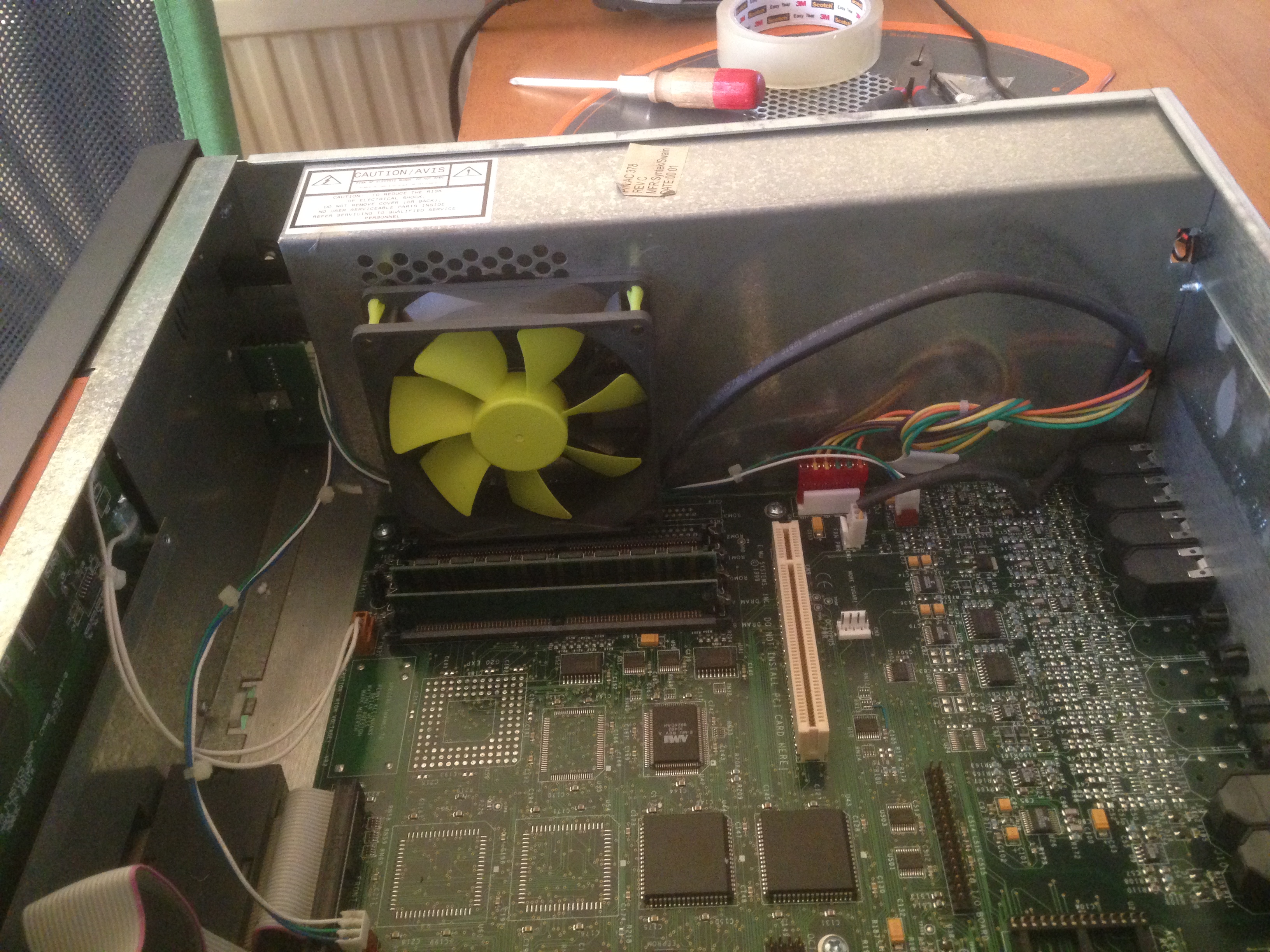
You can then attach the fan using the special rubber screws which dampen vibration noise. Any parts of the grill which remain exposed should be taped over to stop airflow. I’ve used clear tape here so it’s not visible in the picture.
(Silent fan fitted to power supply housing)
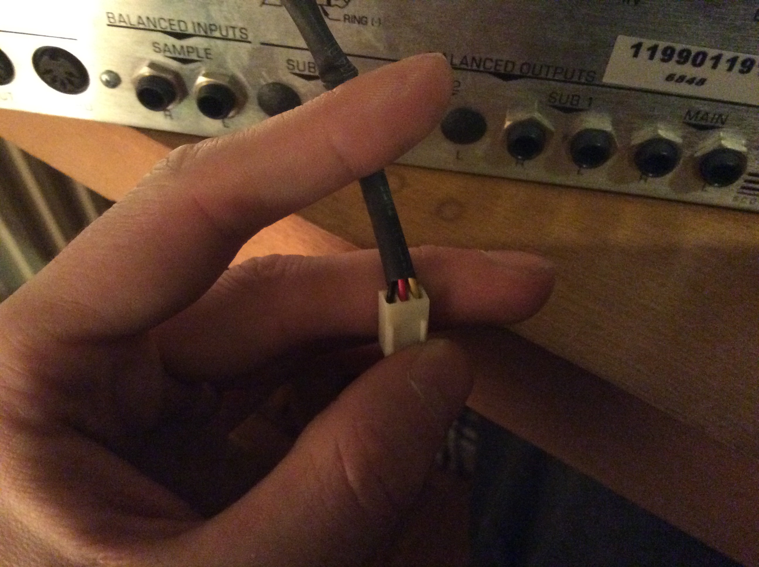
The fan power cable will need to be plugged in backwards to the samplers motherboard, so clip off the two plastic burs on the connector.
(fan power connector, yellow goes to NC, red to +12v, black to ground)
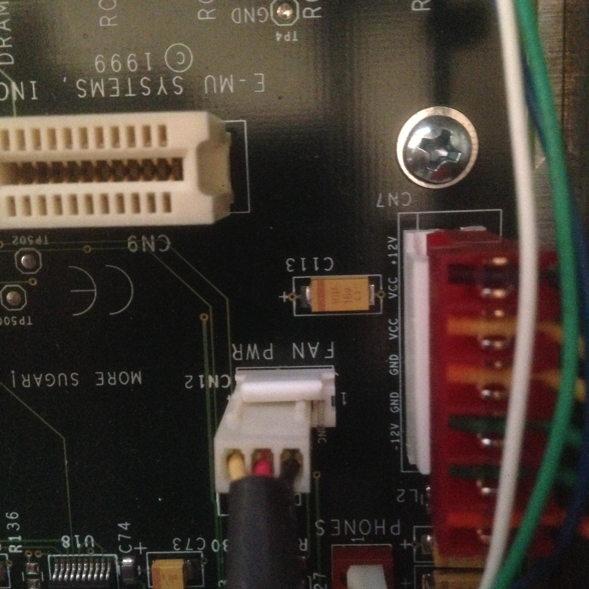
Now connect the fan to the motherboard power header. The motherboard header has 4 pins but the fan only has 3 so you have to be careful to connect it the right way round.
If you are facing the rear of the sampler you want to plug the 3 pin fan connector in to the 3 pins on the left hand side of the motherboard connector, making sure that the side of the fan connector with the removed burs is touching the plastic side of the fan power header.
If you’ve got it the right way round you will be able to see that the yellow wire is going to “NC”, the red to “+12v” and the black to “grnd.”
fan in place
You can now carefully reassemble the case screwing the rear fan grill back on with the two screws and nuts and then reattaching the power supply housing.
Reconnect the power plug and power on the sampler to make sure that the fan is spinning well and not making any noises. If all’s well, power off, screw the case back on and voila.
Enjoy the silky smooth sound of nothing. (Well virtually)
To properly silence this thing, I’ve also done a 2.5″ SATA to IDE mod on the E-MU so that I could get rid of the racket made by my external SCSI drive. I’ll try and document this when I get another free moment.