I picked up a second hand Akai MPC 2500 a few ago and after tricking it out with the full 128mb of ram, a 40gb hard drive and jjosxl I’ve been having great fun breaking my musical shackles from the computer.
Ok, so the MPC is a computer but the hands on tactile feel make the whole experience much different and I’ve found the learning curve minimal given I have a strong background in music technology although I’m sure I still have much to learn as jjosxl seems to be quite deep.
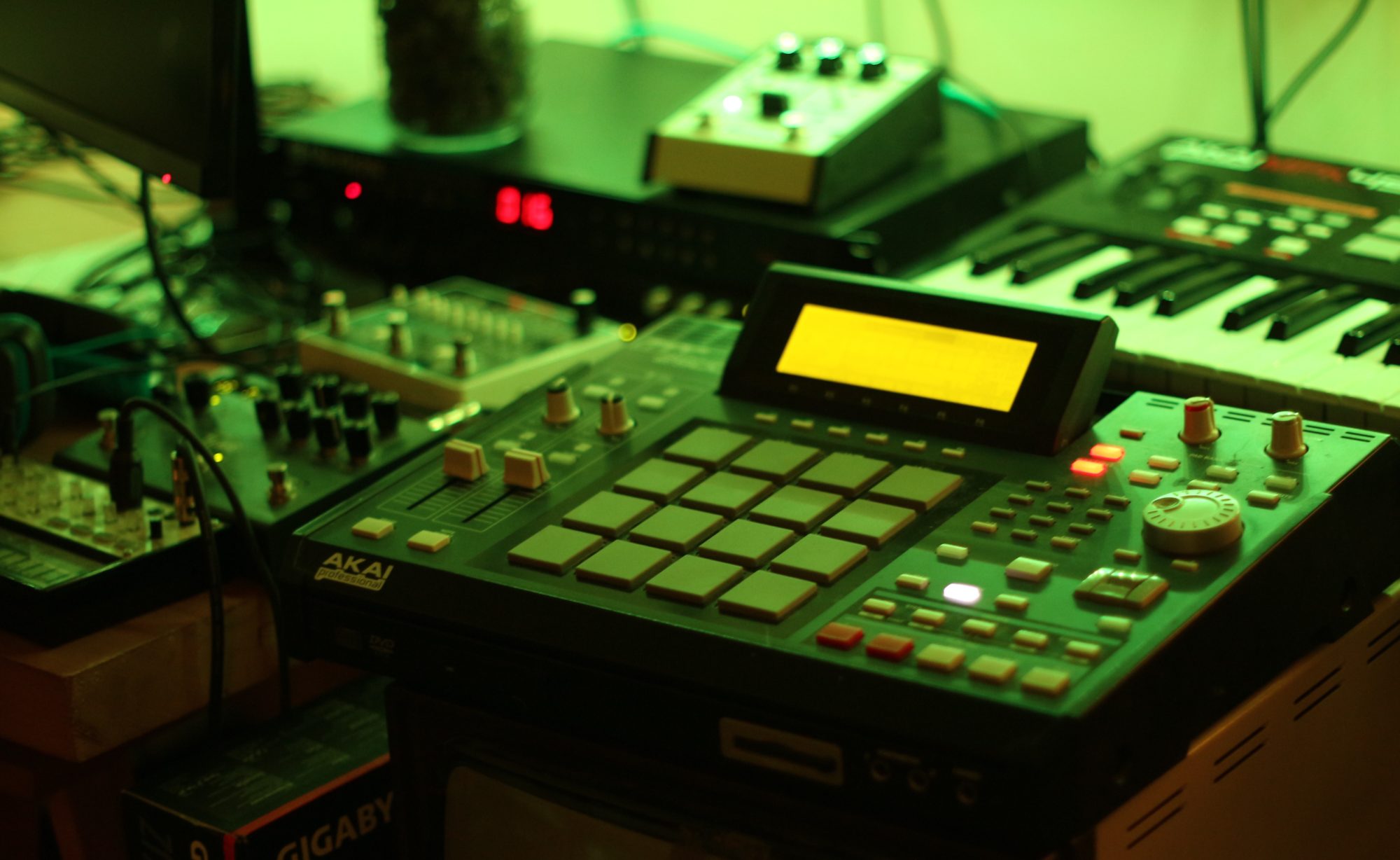
Here are a few tracks I’ve uploaded to Youtube from the last week or two staring the Akai MPC 2500, Korg MS-20 Mini, Korg Volca Keys, Korg Electribe EMX1, Oberheim Matrix 1000, EMU E5000 Ultra, Roland TR-707 and a bit of delay and reverb.
I’ve been trying a few different methods of connecting modern hard drives to my E-MU sampler. My aim, to reduce the noise to an absolute minimum with the side benefit of possible requiring less power from the ageing PSU.
Power
One of the quirks of the e-mu e5000 ultra and other samplers in the range, is that the power output header on the motherboard for internal hard disks has had it’s pins reversed in order of a standard PC. Plugging in a hard drive to the sampler and turning it on without modifying the power cable will result in +12v being where your hard drive expected +5v and a puff of magic smoke will signal the death of your hard drive.
SATA to IDE coverters
I tried several different converters without success until I came across the WinTech 93205-GB which worked great with standard 2.5″ spinning SATA disks but although SATA SSD drives were detected by the sampler they were not able to be formatted or accessed when pre-formatted as FAT.
The WinTech has a slide switch to select between host and device. Device was selected.
Wintech 93205-GB SATA to IDE Converter
The fix for the reverse power connection was simple, clip through all the cables and connect the red to the yellow and the yellow to the red, swap the ground cables and test with a multimeter to make sure I hadn’t made any mistakes. I took this opportunity to also solder in the tiny 5v power connector for the WinTech in series from the 5v power cable and ground.
Doctored power cable
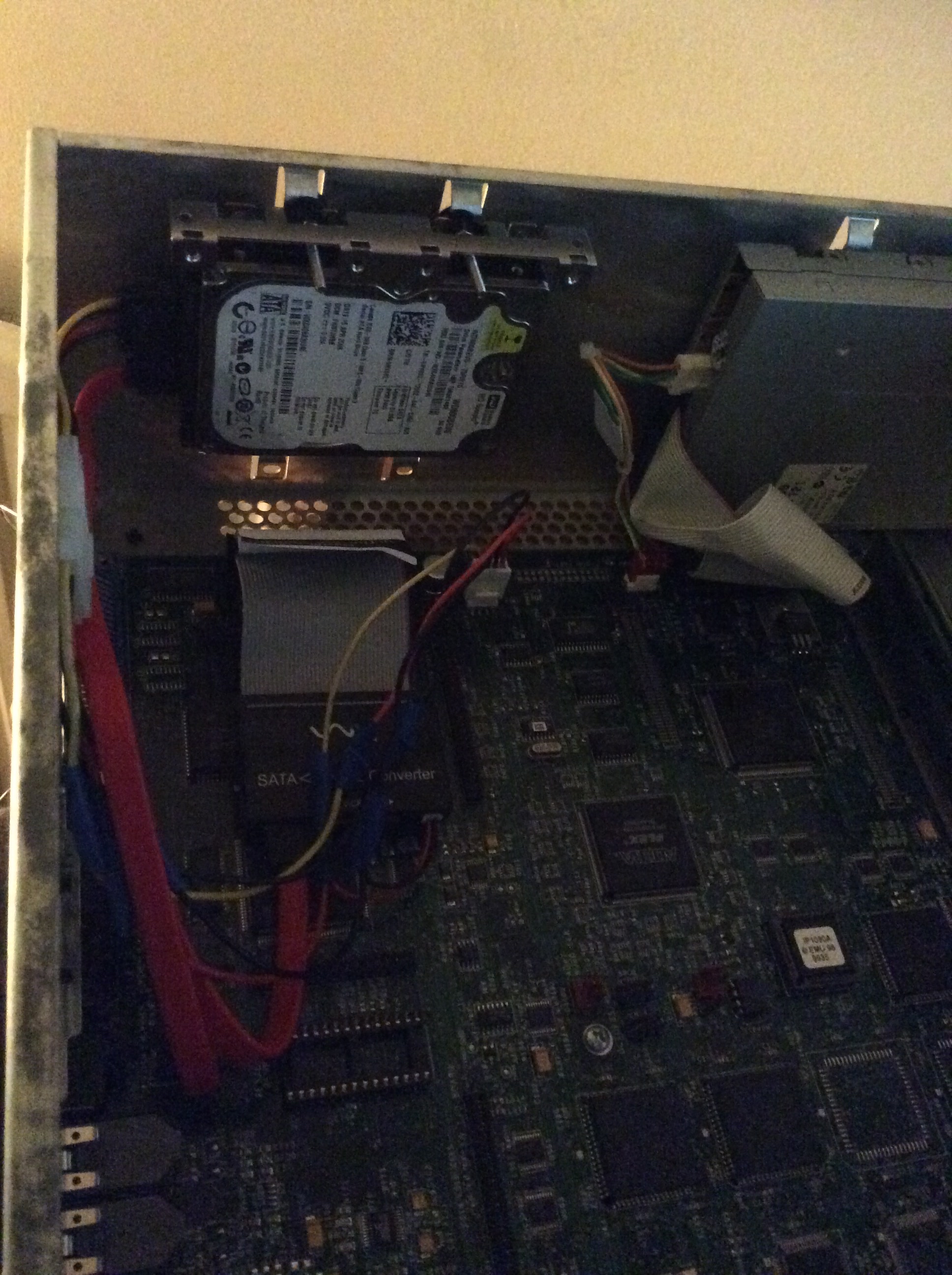
To connect the hard drive to the case I used a 2.5″ to 3.5″ mounting bracket with rubber washer to reduce vibration noise and fixed to the top mounting holes for a 3.5″ disk.
Mounted in position
Lovely, barely a sound and worked flawlessly.
I wanted more though.
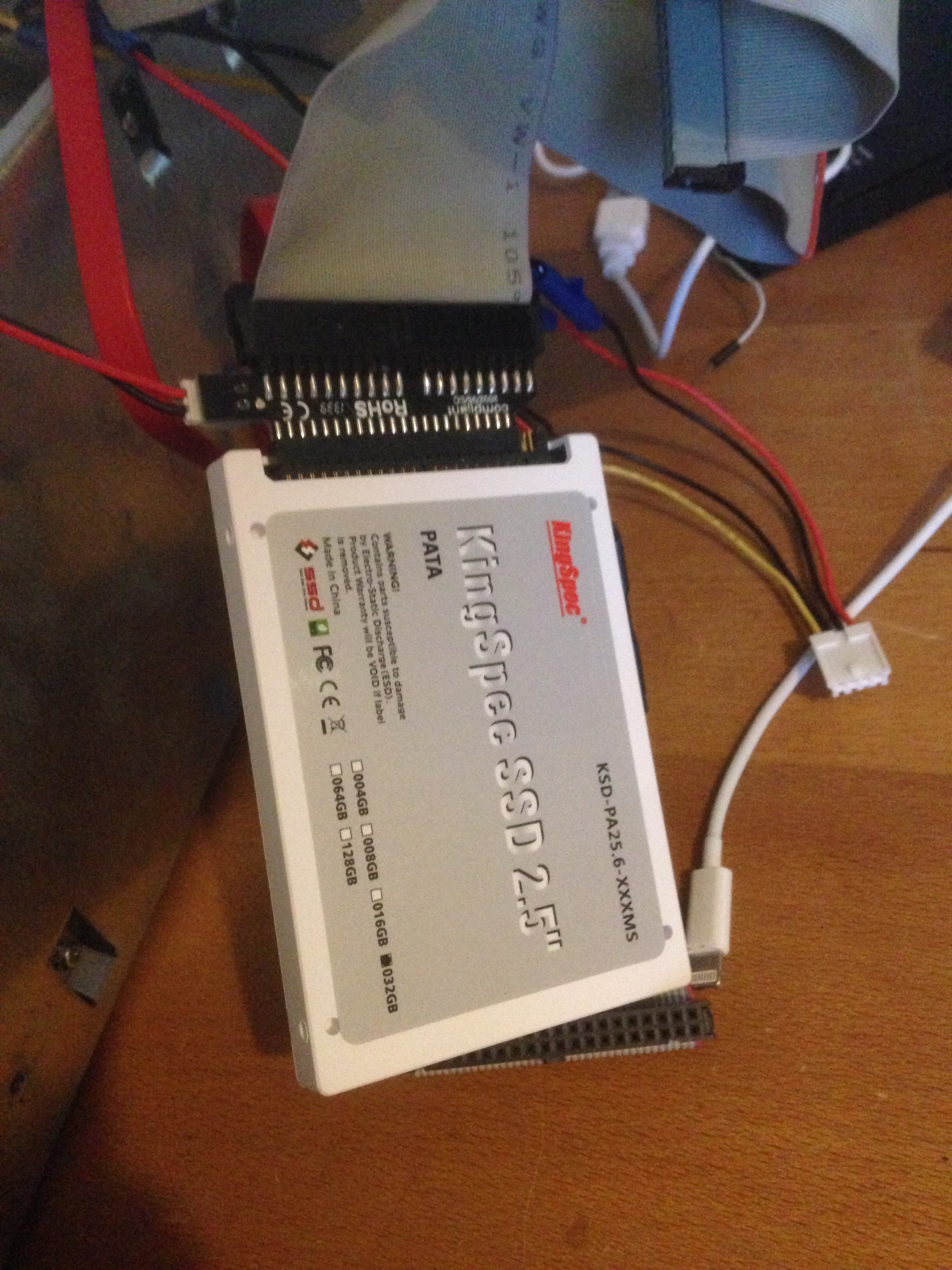
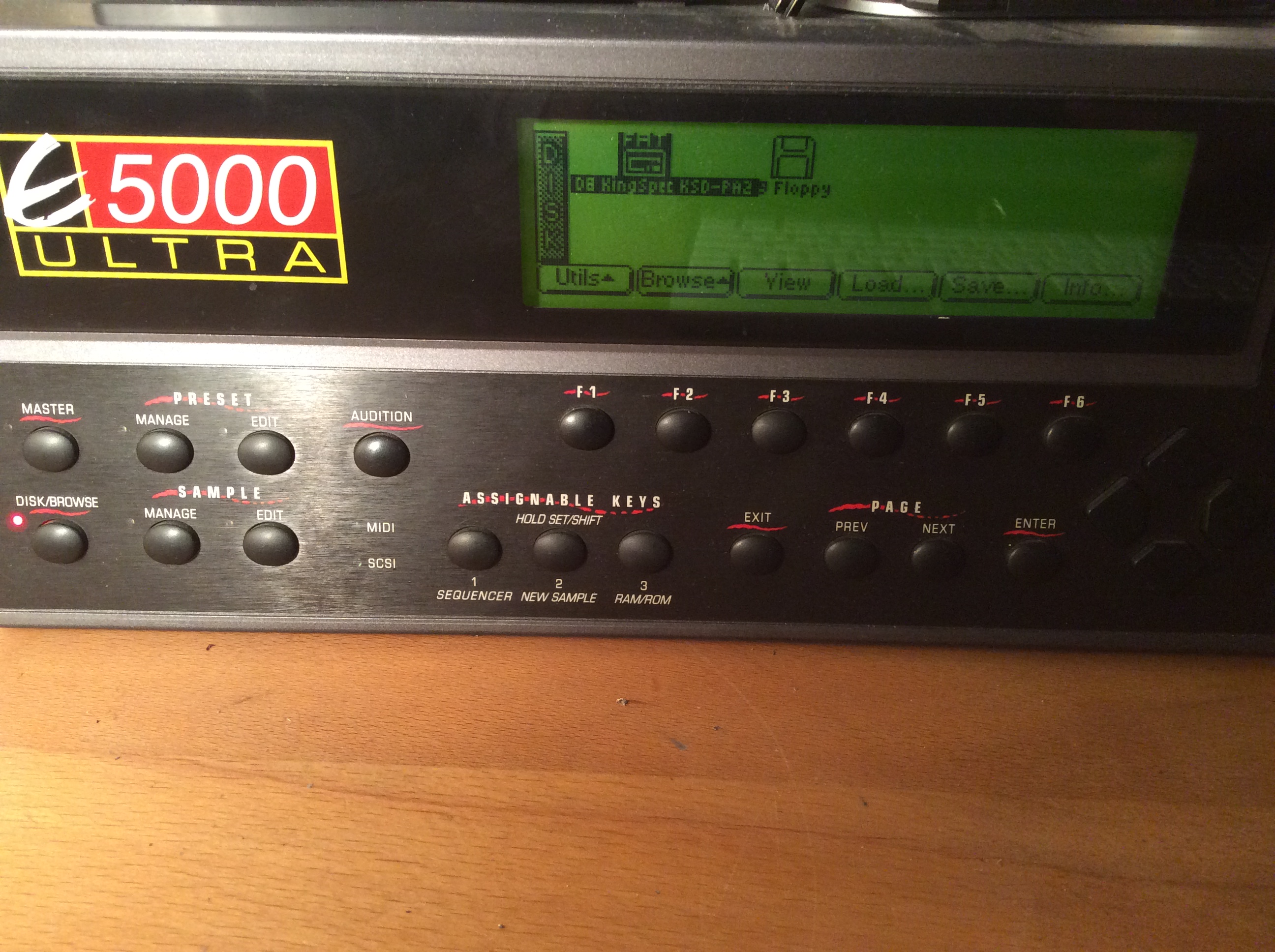
PATA SSD
I took to google in a quest to find myself a IDE/PATA SSD hoping that it just might work.
Hello all, I thought I’d document the process of replacing the noisy power supply fan in my E-MU E5000 Ultra sampler with some pictures in the hope that it may be of use to others out there.
All credit goes to GaemethProject‘s video on YouTube for giving me the confidence to try this myself.
First off you’ll need the following tools and components;
It’s worth keeping in mind that the large capacitors in power supplies can retain a charge for some considerable time after being powered off so make sure to wait at least a few hours with the machine turned off and unplugged before attempting access to the power supply. I’m probably over cautious but I’d like to wait at least a day.
Once an appropriate amount of time has passed, you can begin by removing the 7 screws holding the case lid in place, 2 on each side and then 3 at the top of the rear.
Now that you have access to the inside of the case, you can move to the back and start unscrewing the screws which hold the power supply housing in place. Make sure not to undo the two screws holding the fan in-place until after you have removed the power supply housing.
(Screws holding E-MU E5000 Ultra fan and psu housing in place)
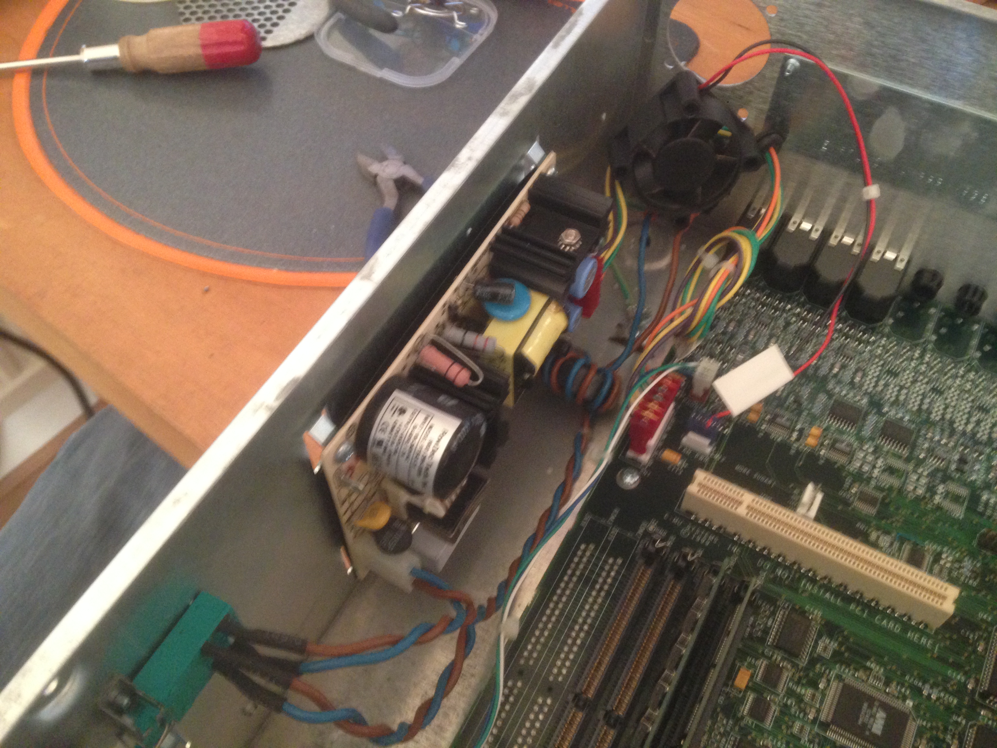
Now with a bit of jiggling you will be able to remove the power supply housing, be careful not to damage any of the cables which are threaded through the housing or the on off switch which is partially housed behind the power supply case but does not need to be removed.
(The power supply revealed)
You can now unplug the fan from the header pins on the motherboard and throw it in the bin. (Ok, you can keep it if you want to but why would you want to?)
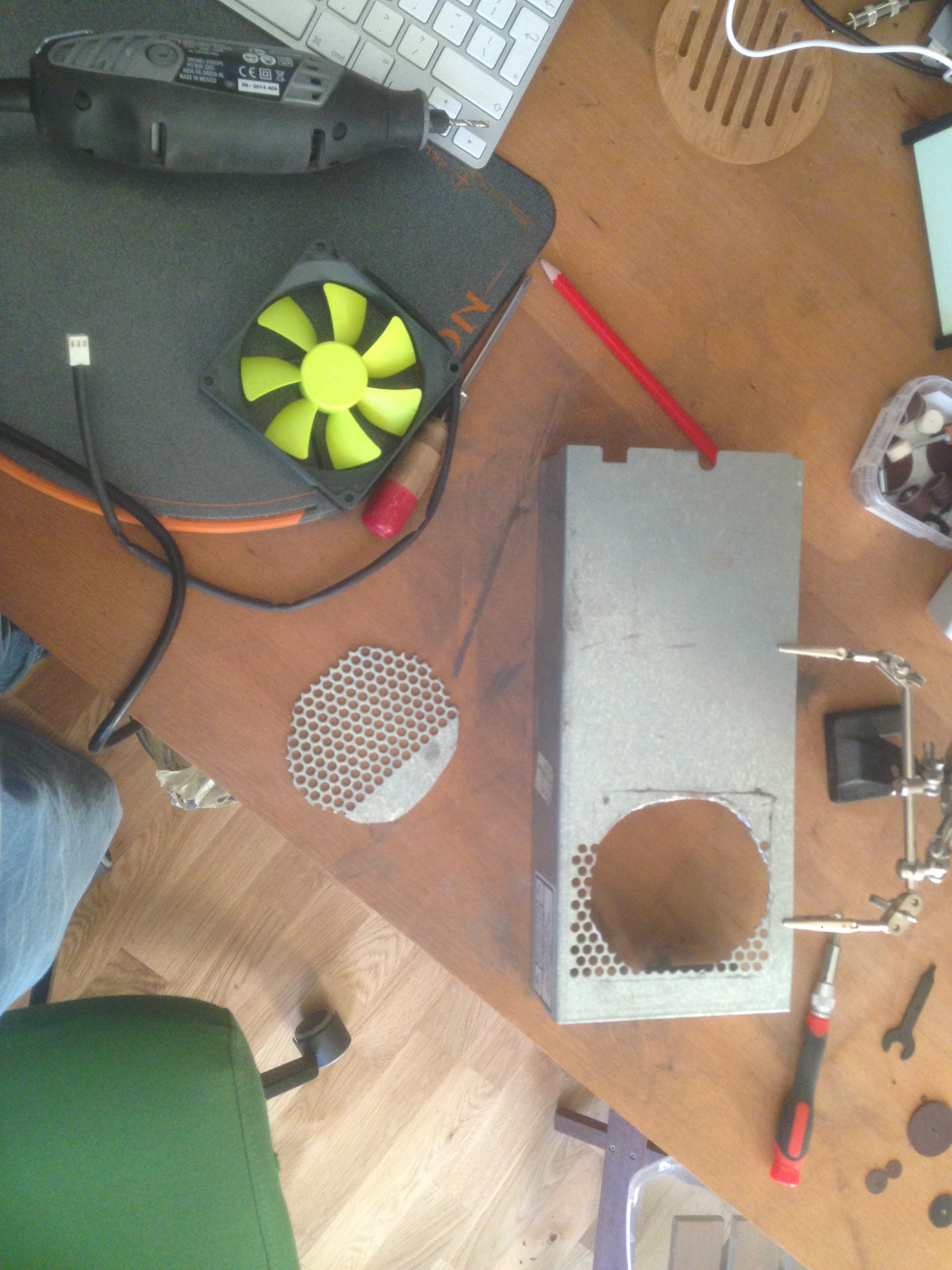
Now that you have the power supply housing free it’s time to get busy with the Dremel. Try positioning your new fan over the grill to to see where it will fit best. You should be able to use two of the holes in the grill for two of your fan fixings.
Once you’ve got it nicely lined up you can try and use a felt tip or pencil to mark up a few guide lines and then cut out the section.
(Section cut out of power supply grill)
You’ll also need to drill two holes for the other two screws of the fan.
You can then attach the fan using the special rubber screws which dampen vibration noise. Any parts of the grill which remain exposed should be taped over to stop airflow. I’ve used clear tape here so it’s not visible in the picture.
(Silent fan fitted to power supply housing)
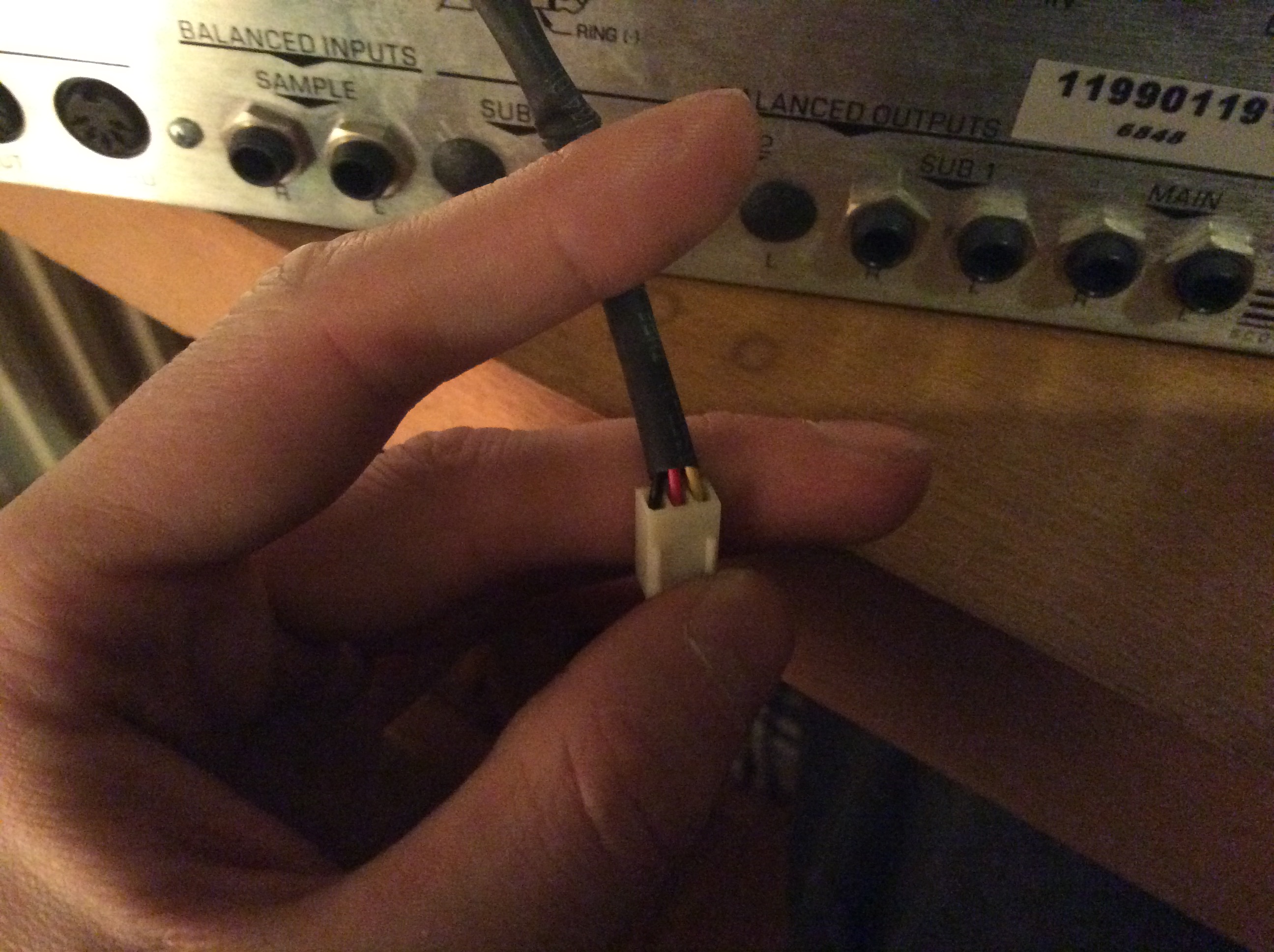
The fan power cable will need to be plugged in backwards to the samplers motherboard, so clip off the two plastic burs on the connector.
(fan power connector, yellow goes to NC, red to +12v, black to ground)
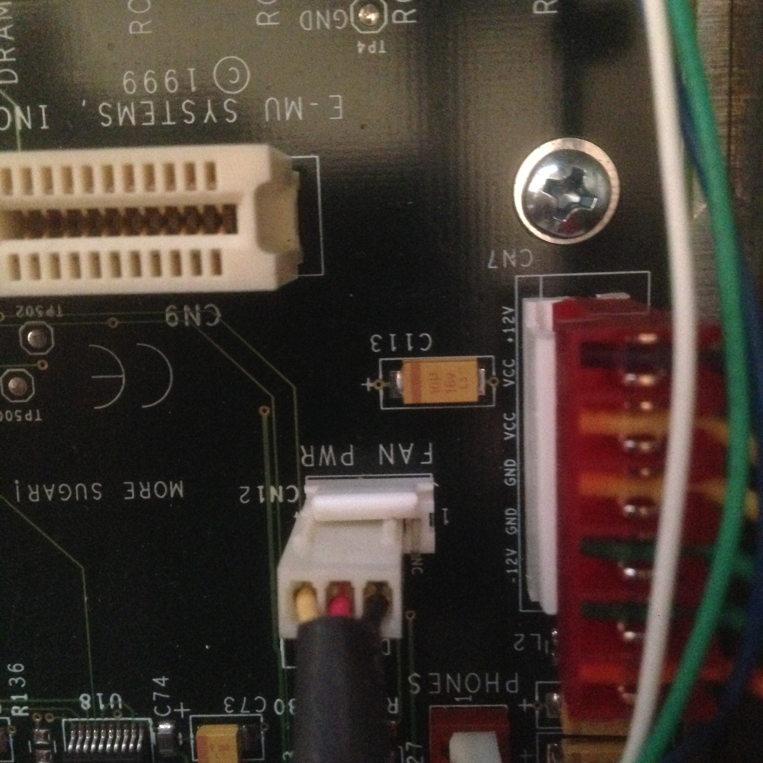
Now connect the fan to the motherboard power header. The motherboard header has 4 pins but the fan only has 3 so you have to be careful to connect it the right way round.
If you are facing the rear of the sampler you want to plug the 3 pin fan connector in to the 3 pins on the left hand side of the motherboard connector, making sure that the side of the fan connector with the removed burs is touching the plastic side of the fan power header.
If you’ve got it the right way round you will be able to see that the yellow wire is going to “NC”, the red to “+12v” and the black to “grnd.”
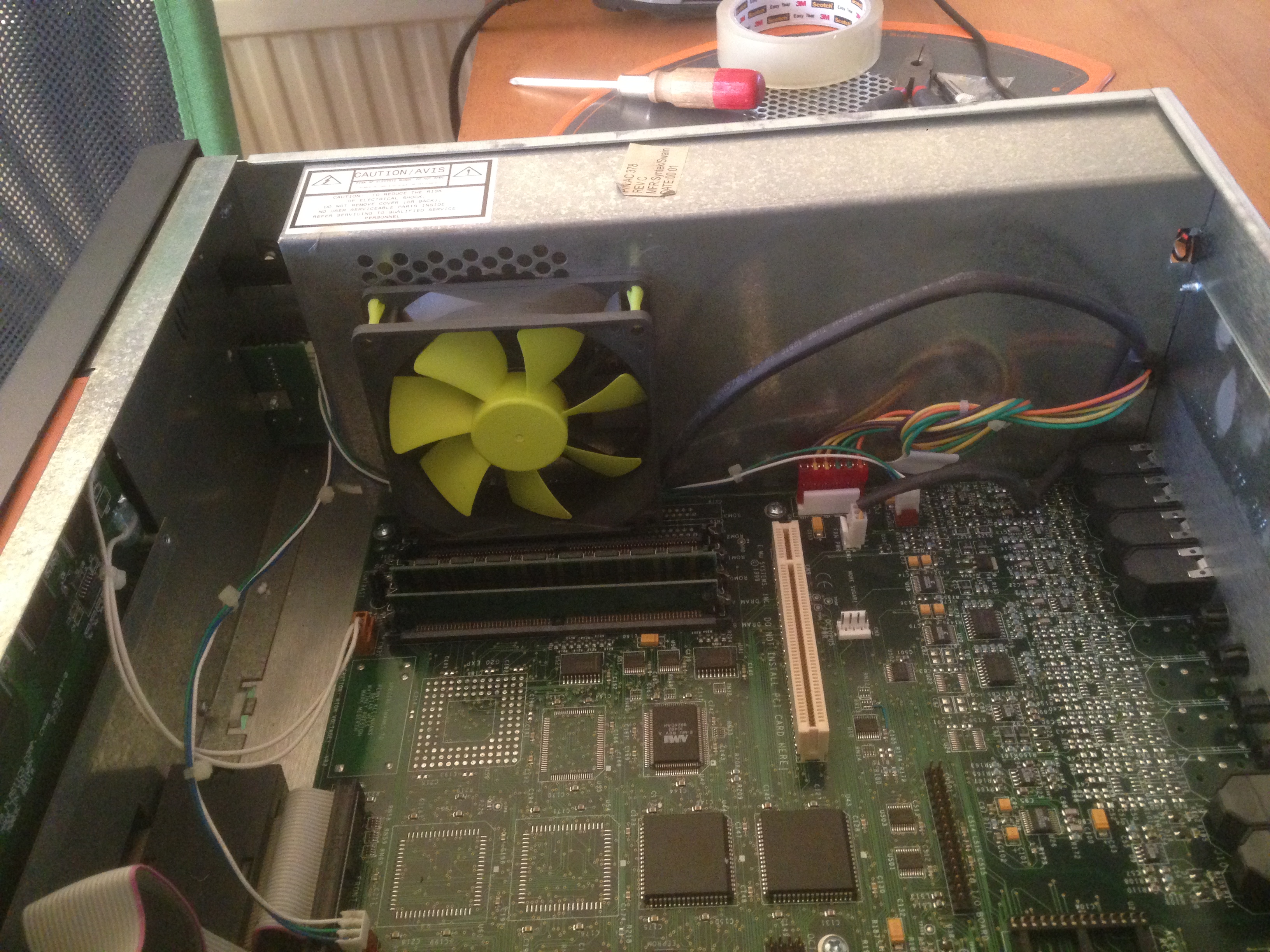
fan in place
You can now carefully reassemble the case screwing the rear fan grill back on with the two screws and nuts and then reattaching the power supply housing.
Reconnect the power plug and power on the sampler to make sure that the fan is spinning well and not making any noises. If all’s well, power off, screw the case back on and voila.
Enjoy the silky smooth sound of nothing. (Well virtually)
To properly silence this thing, I’ve also done a 2.5″ SATA to IDE mod on the E-MU so that I could get rid of the racket made by my external SCSI drive. I’ll try and document this when I get another free moment.