
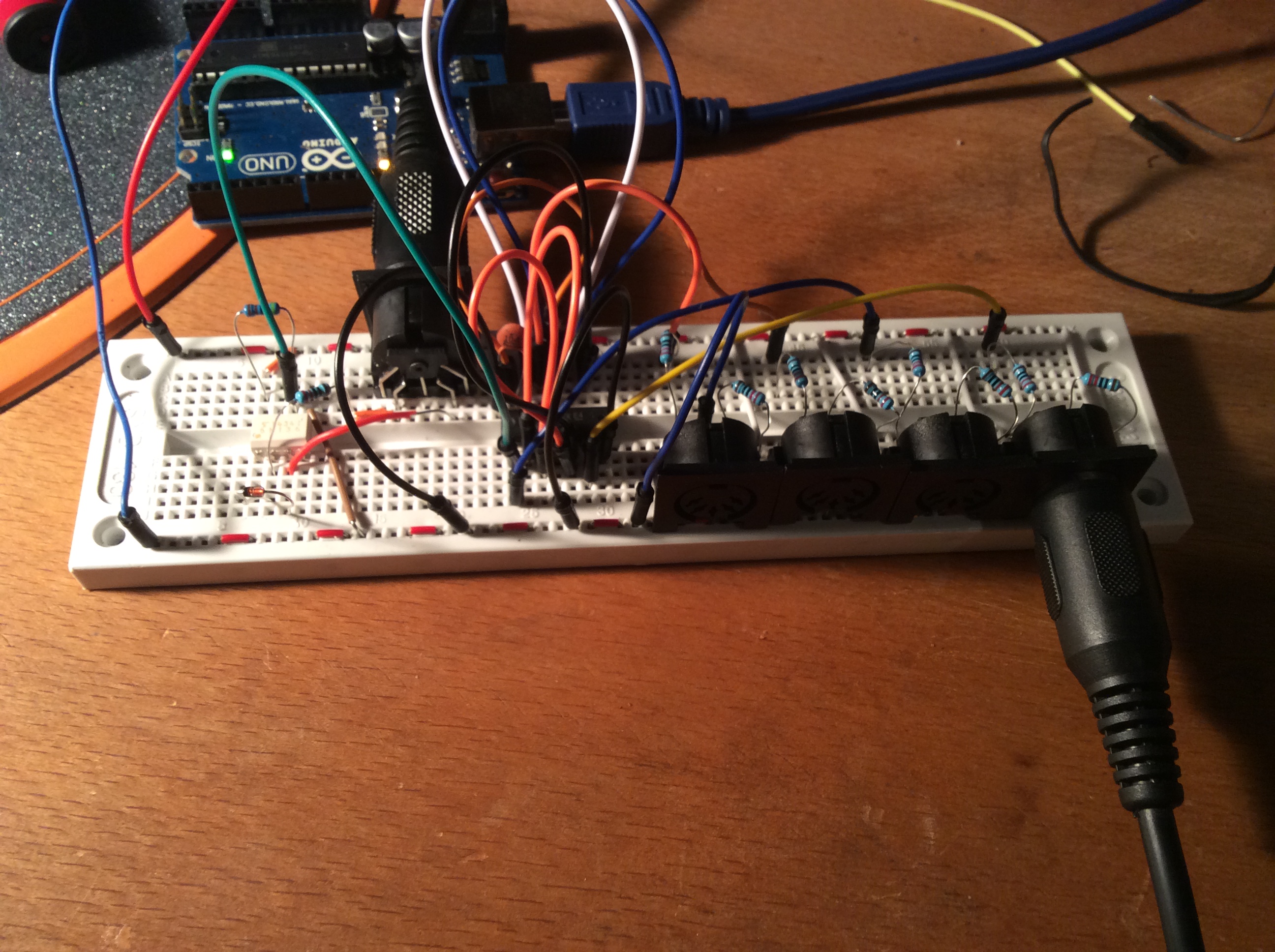
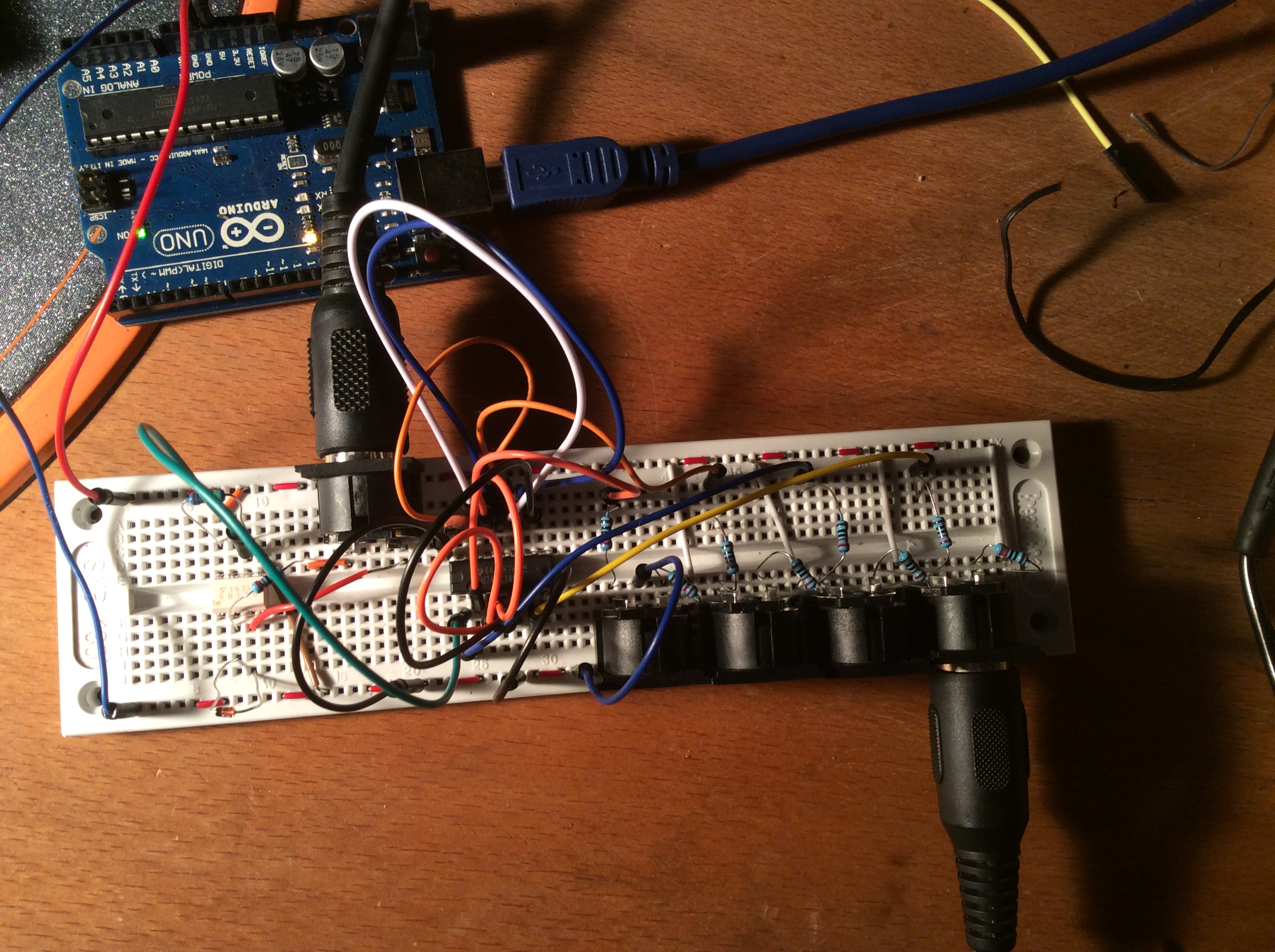
Tonight I’ve been trying to decipher the various schematics online for creating a midi thru box. My knowledge of electronics is growing but still very basic and even such a simple circuit gave me some headaches.
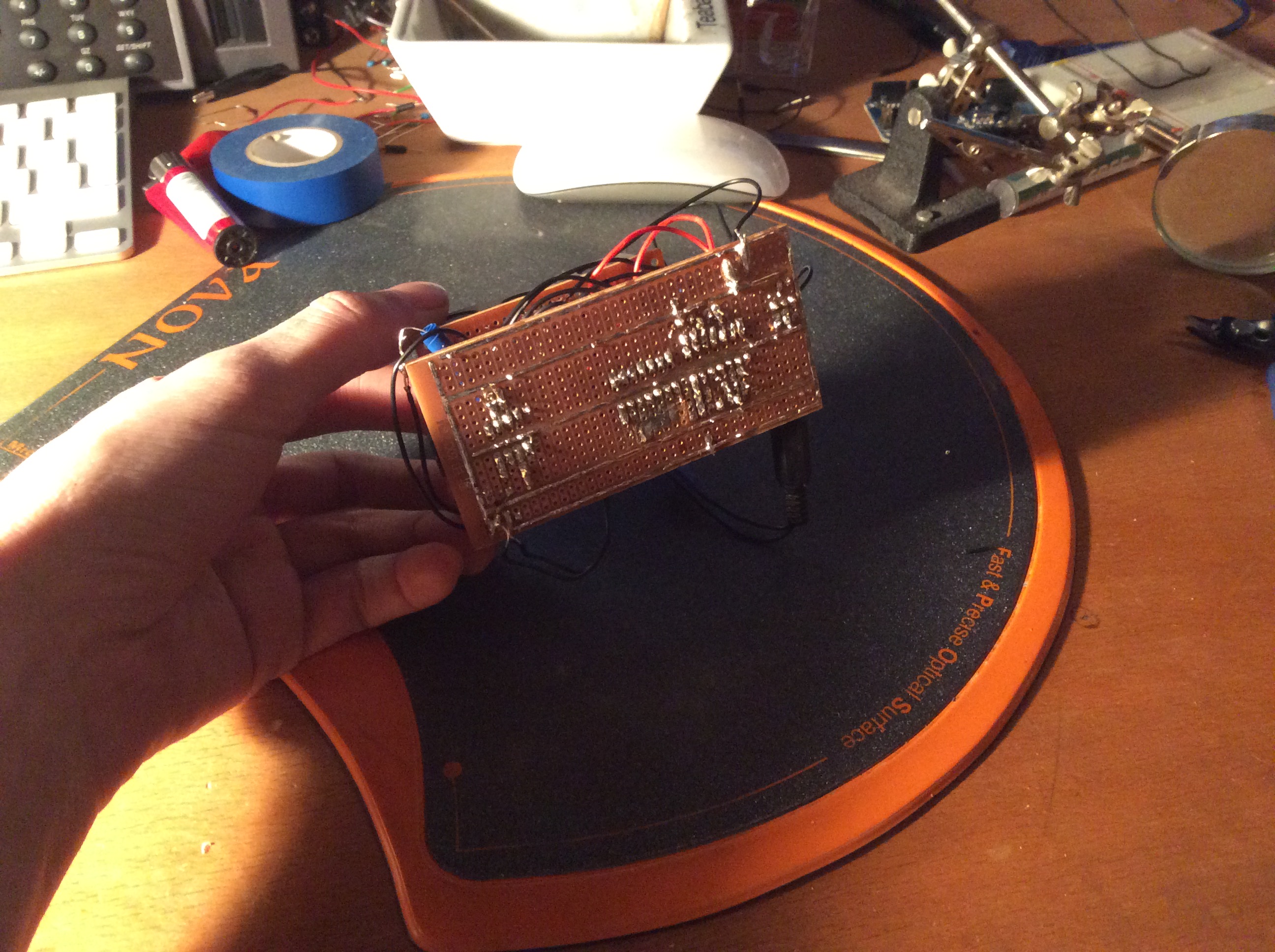
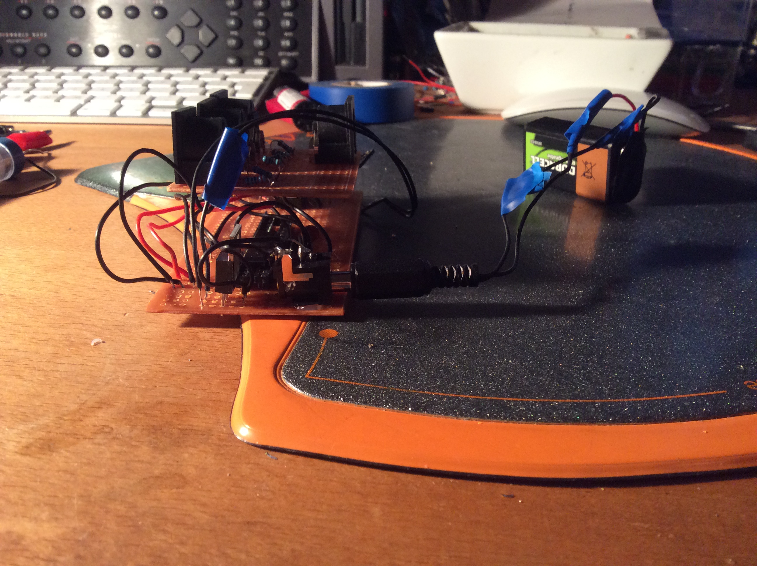
So here it is, a working midi thru, ignore the Arduino connected to the breadboard it’s only being used to supply 5v and nothing else. The soldered circuit board bellow has a 9v battery/mains input.
Bill of materials:
5 x MIDI connectors
1 x 6N136 optocoupler
1 x 74CH14 Hex schmitt inverter (or CD40106)
9 x 220 ohm resistor
1 x 4.7k ohm resistor
1 x 1n4148 diode
1 x TS7805 5v power regulator
1 x 2.1 mm power header


And then solder to perfboard circuit board. It’s certainly not pretty and some of the worst soldering I’ve ever seen but it works. 🙂
All I need now is some sort of case and I’m good to go.


I’ll try and update this post with more detail and clearer breadboard layout / schematic when I get the time.